It does pain me to say that I was not able to get a good model from the drone photos that day. I really wanted to post the model and say, "Look what we were able to do!" But we were not able to get that model. I would not say that the efforts were wasted in anyway. As long as you learn lessons to improve your process and efforts in the future, the project is not a failure.
So what are the lessons we learned?
Lesson #1: You need more than 31 photos
I always try to get a minimum of 50 photos. ReCap's maximum of 250 photos really is best. I got about 31 then let my son fly the drone. His flight ended in a tree, and it took us about 30 minutes to get the drone down. I guess we could have try to fly again. However, I only have two batteries and was worried that I was low on power. The model of drone I have behaves poorly when low on power.
Lesson #2: Pick Frisbees of VERY different colors
When I grabbed a Red and Pink Frisbees, I thought they they may seem too similar in the photos. Then I thought that because the colors were significantly different I would be okay. From the vantage point of the drone, with the sun glaring off the them, it was at times difficult to tell the red from the pink. If I had trouble, I have to assume the software had trouble with telling them apart.
Lesson #3: My hobby quality drone does not fly stable enough for this process
I love drones. For me the appeal is equally how much fun they are to fly and the aerial photography and videos. My drone is so light and is at the mercy of the wind. We only had 6 MPH winds that day and my drone was still pushed very strongly by the wind. Most professional quality drones have GPS and flight planning abilities. Where those are not a mandatory feature for this process, they can make it easier to fly the site and can improve the quality of the results.
Lesson #4: My kids love to run around A LOT
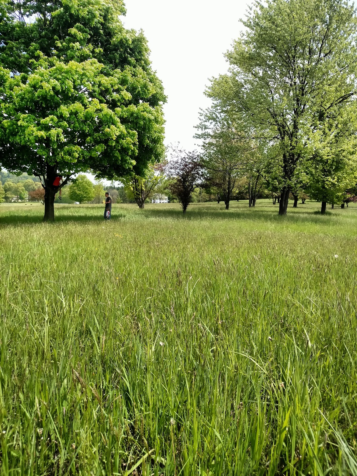
If you look in the photos, my kids did not stay in one place. In fact, they were all over the field, and I have the pictures to prove it. ReCap has no way to filter out my daughter in the photos and work around her. To ReCap she is a feature in the field and tried to match and her surroundings in the photos. So as she went from end to end of the field, ReCap was assuming she was stationary, and this movement confused the results. For ReCap to work right, you really want to try to keep the area clear, as much as reasonable. If I had 250 photos, the movements by my daughter would not have confused ReCap as much.
I was so disappointed that I did not get some really meaningful results. I know the process works, I have seen the process work. I guess it is safe to say that you will not be seeing any advertisements for Olson & Kids Surveying anytime in the future. Well maybe if I can convince my wife to let me get a professional quality drone...Just kidding.
Friday, June 17, 2016

Thursday, June 2, 2016
Current Survey Technology: Part 2 Data Processing
The Processing of the Data is pretty simple, thanks to the ReCap 360 Pro workflow. On the ReCap 360 Pro website, I can start a new "Photo to 3D" project. All I have to do is upload the photos identify the control points.
When I pick a control point in a photo, I can then enter the coordinates for that point. I can even enter the information in Latitude, Longitude, and Elevation format. In my case, the MapIt - Mobile app gave me the Latitude and Longitude, so I had to use the USGS website to get the elevations for my control points.
When identifying the control points, it is feasible to identify the points in as many photos as possible. I have tried this in the past, and it has really overloaded the system. Autodesk's official opinion is that you are to let the software auto register the photographs. Which is what I would do if I was not trying to properly geolocate the model, and have it scaled properly. So I try to identify the control points in about 3 photos.
After the manual registration process, I can pick my output file types and let the system process the model. When it comes to output files, I always pick RCS and ORTHO for Survey based models. The RCS can be loaded into the ReCap desktop application. I will sometimes include the RCM, which is the Autodesk Memento file format. I will occasionally include this so I have it if I want to load the model into Memento.
Here is a Screencast that demonstrates the process.
When I pick a control point in a photo, I can then enter the coordinates for that point. I can even enter the information in Latitude, Longitude, and Elevation format. In my case, the MapIt - Mobile app gave me the Latitude and Longitude, so I had to use the USGS website to get the elevations for my control points.
When identifying the control points, it is feasible to identify the points in as many photos as possible. I have tried this in the past, and it has really overloaded the system. Autodesk's official opinion is that you are to let the software auto register the photographs. Which is what I would do if I was not trying to properly geolocate the model, and have it scaled properly. So I try to identify the control points in about 3 photos.
After the manual registration process, I can pick my output file types and let the system process the model. When it comes to output files, I always pick RCS and ORTHO for Survey based models. The RCS can be loaded into the ReCap desktop application. I will sometimes include the RCM, which is the Autodesk Memento file format. I will occasionally include this so I have it if I want to load the model into Memento.
Here is a Screencast that demonstrates the process.
Wednesday, May 25, 2016
Current Survey Technology: Part 1 Data Collection
The current landscape of survey and survey technology is dramatically changing very quickly. What used to take crews of highly skilled individuals days or weeks to accomplish can be achieved in minutes, with one or two individuals. I thought it would be fun to take the next couple blog posts and outline what is possible with the current technology, and how this can be done with smaller crew of people with a different skill set.
I was especially excited for this topic because it blends a lot of my passions together. I am a little bit of a technology junkie. I am always interested to see the newest technology and ways are using said technology. This topic also gives me the opportunity to fly my drone. I caught the drone bug when working with a customer on a project. Now, my son and I both have drones. Don't worry, I am fully complaint with the current drone laws. Lastly, my kids are very interested in what I do. My two oldest are home-schooled and a small part of their curriculum is what we call "CAD with Dad." CAD with Dad is time we set aside for me to teach them what I do. My oldest (12) has been using Inventor for over a year now, and my middle child (7) has about 6 months of experience.
This post is going to be dedicated to the data collection phase of our project.
The Team

Steve (Me)
My Son (12)
My Older Daughter (7)
My Youngest Daughter (2)
So you can see that, I am the only experience person on the team. I have zero experience with traditional survey techniques, but I have seen the process many times. I have a very good understanding of the key steps of a survey using the newest technology. Realistically, my youngest was along for the ride, and she gets really upset when anyone goes somewhere without her.
Our Equipment
My Cell Phone
The main role of my cell phone is to use a GPS App that would give me the coordinates of a few select points. In this case, I used MapIt Mobile.
My Drone

My Drone is a Syma X8G. It is a toy/hobbyist model. I got it from Amazon. I does not have any GPS or First Person View (FPV) capabilities. So it is nothing special, there are a whole host of models that are better suited for this type of procedure. However, this was a good model that fit into my budget and is a lot of fun otherwise.
Different Colored Frisbees

This is a key element to the process, but they do not need to be Frisbees. It is important to have points with known coordinates. I chose to mark them with Frisbees, but anything would work. It just so happens that we had some Frisbees laying around that were different colors. I feel that it is good to have them be uniquely identified. The software will work better when it can tell the difference between your markers. Frisbees are great because they lay flat, and will not give you a raised section in your resulting point cloud. I have also seen people use the lids to 10 gallon buckets or a large white X on the ground. If you plan on flying an area multiple times, it will be beneficial to have the markers held in place in some fashion. Spray painting markers are a good idea as well, there is just the issue of the how permanent the paint will be. In some smaller projects, I have used round stickers.
The Job Site
There is a nice open field less than a 1/2 mile from where we live. I figured that would be a nice open field to perform this task on.

The Process
We laid out the Frisbees, being careful to note the coordinates of the Frisbee locations. My youngest wanted to pick them up and move them, which would not be a problem for a typical survey crew. We then flew the drone over the site, trying to make sure that we got the Frisbees in as many shots as possible. Since my drone does not have the First Person View (FPV) capabilities, we had to just hope that we got them in the pictures, which we did pretty good. For some extra shots, I had my 7 year old, take some pictures with my cell phone.
My goal was to get as many shots as I could. ReCap has a limit of 250 photos per task. In our attempt we did not get nearly that many for two reasons. One my drone is so light, it gets pushed by the wind pretty severely, so it was hard to control it around the project site. The other reason is that my son, how is a pretty experienced drone pilot, flew the drone into a tree and got it stuck.

I was especially excited for this topic because it blends a lot of my passions together. I am a little bit of a technology junkie. I am always interested to see the newest technology and ways are using said technology. This topic also gives me the opportunity to fly my drone. I caught the drone bug when working with a customer on a project. Now, my son and I both have drones. Don't worry, I am fully complaint with the current drone laws. Lastly, my kids are very interested in what I do. My two oldest are home-schooled and a small part of their curriculum is what we call "CAD with Dad." CAD with Dad is time we set aside for me to teach them what I do. My oldest (12) has been using Inventor for over a year now, and my middle child (7) has about 6 months of experience.
This post is going to be dedicated to the data collection phase of our project.
The Team

Steve (Me)
My Son (12)
My Older Daughter (7)
My Youngest Daughter (2)
So you can see that, I am the only experience person on the team. I have zero experience with traditional survey techniques, but I have seen the process many times. I have a very good understanding of the key steps of a survey using the newest technology. Realistically, my youngest was along for the ride, and she gets really upset when anyone goes somewhere without her.
Our Equipment
My Cell Phone
The main role of my cell phone is to use a GPS App that would give me the coordinates of a few select points. In this case, I used MapIt Mobile.
My Drone

My Drone is a Syma X8G. It is a toy/hobbyist model. I got it from Amazon. I does not have any GPS or First Person View (FPV) capabilities. So it is nothing special, there are a whole host of models that are better suited for this type of procedure. However, this was a good model that fit into my budget and is a lot of fun otherwise.
Different Colored Frisbees

This is a key element to the process, but they do not need to be Frisbees. It is important to have points with known coordinates. I chose to mark them with Frisbees, but anything would work. It just so happens that we had some Frisbees laying around that were different colors. I feel that it is good to have them be uniquely identified. The software will work better when it can tell the difference between your markers. Frisbees are great because they lay flat, and will not give you a raised section in your resulting point cloud. I have also seen people use the lids to 10 gallon buckets or a large white X on the ground. If you plan on flying an area multiple times, it will be beneficial to have the markers held in place in some fashion. Spray painting markers are a good idea as well, there is just the issue of the how permanent the paint will be. In some smaller projects, I have used round stickers.
The Job Site
There is a nice open field less than a 1/2 mile from where we live. I figured that would be a nice open field to perform this task on.

The Process
We laid out the Frisbees, being careful to note the coordinates of the Frisbee locations. My youngest wanted to pick them up and move them, which would not be a problem for a typical survey crew. We then flew the drone over the site, trying to make sure that we got the Frisbees in as many shots as possible. Since my drone does not have the First Person View (FPV) capabilities, we had to just hope that we got them in the pictures, which we did pretty good. For some extra shots, I had my 7 year old, take some pictures with my cell phone.
My goal was to get as many shots as I could. ReCap has a limit of 250 photos per task. In our attempt we did not get nearly that many for two reasons. One my drone is so light, it gets pushed by the wind pretty severely, so it was hard to control it around the project site. The other reason is that my son, how is a pretty experienced drone pilot, flew the drone into a tree and got it stuck.
These two issue are examples of why a professional quality drone would be best for these tasks. With drones that have GPS capabilities, users have the ability to program a flight plan, and the drone will fly itself. Also, these drones can take measures to adjust to stronger winds.
In my next post, I will talk about the procedure to take the photos into ReCap 360 to generate a point cloud.
Tuesday, May 17, 2016
A Quirk With iParts
Recently, I received an email from someone that saw one of
my videos on YouTube. They had watched
the video that talked about how to read the iPart Table to get values for other
components. They had successfully copied
the code and applied to their model.
However, they were getting an error stating that Inventor could not read
the iPart table.
The error message really through me because he clearly had
an iPart and he had the correct syntax.
I had asked this user to send me his model so that I could see it first
hand, and maybe the source of the problem would hit me. While I waited, I happened to stumble upon
this persons Inventor Discussion Group post regarding separate question on this
model. In reading his Discussion Group thread,
I realized that the component that is giving him grief was not originally an
iPart. He had modeled component the
component as a standard part then placed in the assembly. After that had been done, he had converted
the part to an iPart.
Having that information, I realized the source of the
problem. Inventor has a quirk with
iParts. If you place a standard
component in an assembly, then make that component into an iPart, Inventor does
not realize that it is an iPart. It will
look like an iPart, but some of the iPart behaviors will not work. My theory is that when an iPart is placed,
certain flags are trigged that enable the iPart behaviors. Since the change to the part happens after it
is placed, the flags do not get triggered.
The solution to this quirk is relatively easy. The component just has to be replaced with
itself, using Component Replace. When
browsing for the component to be the replacement, just pick the same part
file. Now the flags will be
triggered. The only problem I have ever
had with this is that the constraints always are broken. Once they are repaired, the component will
behave like an iPart.
Having shared the source and the fix of the issue with the
user I was working with, he applied the fix and his iLogic rule began working
as designed.
Here is a Screencast I recorded to illustrate the issue and proper fix.
This is an issue that has been around as long as I have been
using Inventor. I run into about two or
three times a year, and I don’t know if many people know or understand the
issue. So I wanted to share this with
all of you.
Thanks for reading.
Tuesday, May 10, 2016
Copying iProperties from Model to Drawing
Recently, a customer asked me if it were possible to use iLogic to copy certain iProperties from their model to the drawing. They use certain ones on the title block, but want them in the drawing so they can be searchable in Vault. After thinking about what the code would look like for a little while, I realized that Inventor is capable of doing that right out of the box.
In the Document Settings of an IDW, you can select properties that should be copied from a model. It works right out-of-the-box on standard iProperties. Custom iProperties will need a sample file so that Inventor can build the mapping.
I then realized these setting only produces a one-time push. That is when I discovered the command to "Updated Copied Properties." It was at that moment that I realized that I could automate the process through some iLogic. I have to give a big "kudos" to the "Being Inventive" blog. The heavy lifting of the syncing is thanks to the code that published.
You can see the original "Being Inventive" blog post HERE
You can download the text to the Update Copied iProperties External iLogic rule HERE
Here is my Screencast video that shows how to set this up.
In the Document Settings of an IDW, you can select properties that should be copied from a model. It works right out-of-the-box on standard iProperties. Custom iProperties will need a sample file so that Inventor can build the mapping.
I then realized these setting only produces a one-time push. That is when I discovered the command to "Updated Copied Properties." It was at that moment that I realized that I could automate the process through some iLogic. I have to give a big "kudos" to the "Being Inventive" blog. The heavy lifting of the syncing is thanks to the code that published.
You can see the original "Being Inventive" blog post HERE
You can download the text to the Update Copied iProperties External iLogic rule HERE
Here is my Screencast video that shows how to set this up.
Thursday, May 5, 2016
The Power of Almost Zero
Over my years of using Inventor, I have found times and
scenarios where I need a dimension to be 0 or almost nothing. For those times, I have begun using 0.001 as
my personal approximate 0 value. It
works for both inches and millimeters.
Recently, I even found it useful on an angular dimension.
The beauty of this value is that it relatively unnoticeable on
drawings and models. If the geometry
gets dimensioned on a drawing, the precision of the dimension should round down
to a 0.
So where can the Power of Almost Zero be leveraged?
My original discovery of the Power of Almost Zero was when I
began using iLogic. The specific design
had configurations where a particular value or parameter would be 0 and other
positive values. I created a sketch
driving the dimension with a parameter.
I found that if I set the parameter to 0 then changed to a positive value;
the dimension would randomly push the geometry the wrong way. I knew then that I had to find a way to get
the geometry to stay in the same relative direction of the geometry that I was
dimensioning from. That is when I
figured if I used a value such as 0.001 instead of 0, my geometry would stay on
the same side of the geometry I was measuring from.
I have had scenarios is sheet metal models where I need flanges
to touch. If they touch, Inventor will
“weld” the material in those spots and not flatten the part. However, if there is a 0.001 gap, the part
will be able to flatten. I would have to
say that my most common use of 0.001 in sheet metal models is as the Gap value
for the Rip command.


My previous post referenced a way to use 0.001 as an angular limit
to a Cylindrical Joint.

I truly believe that the Power of Almost Zero can be used in
all kinds of ways. I would love to hear
ways other people have leveraged this power.
Tuesday, April 26, 2016
Restricting Rotation in a Cylindrical Joint
Recently, I was showing a class how to constrain an assembly using the Joint command. For this example, I was using a cylinder subassembly. Typically, the piston will spin when using a Cylindrical joint. When I was showing this to may class, I began to think of how some simulation software packages allow use to lock degrees of freedom in joints.
While looking at the options for the cylindrical joint, I noticed that I could not lock the degree of freedom, but I could apply limits. My first thought was to apply 0 deg for Start, Current, and End values. When I did this, I was still able to spin the part. Then I realized this would be a good application of the "Almost 0 Factor." I use .001 as a value to represent almost 0 in Inventor, I call it the "Almost 0 Factor." I will write a blog about the "Almost 0 Factor" some day soon. When I applied .001 deg as the end value, I got the part to slide, and only rotate a small about. The small amount of rotation was acceptable because you will never notice the rotation.
Here is a Screencast I made that demonstrates the process and outcome.
While looking at the options for the cylindrical joint, I noticed that I could not lock the degree of freedom, but I could apply limits. My first thought was to apply 0 deg for Start, Current, and End values. When I did this, I was still able to spin the part. Then I realized this would be a good application of the "Almost 0 Factor." I use .001 as a value to represent almost 0 in Inventor, I call it the "Almost 0 Factor." I will write a blog about the "Almost 0 Factor" some day soon. When I applied .001 deg as the end value, I got the part to slide, and only rotate a small about. The small amount of rotation was acceptable because you will never notice the rotation.
Here is a Screencast I made that demonstrates the process and outcome.
Thanks for reading,
Steve
Subscribe to:
Posts (Atom)