Monday, March 8, 2021

My First Month with a 3D Printer

I have been wanting a 3D printer for a number of years now but wasn't sure how much use I would get out of it, so it remained a "wish list" item.  Then recently, we realized that it could be used to make 3D stencils for my wife's furniture refinishing business. Initially, I was looking at smaller printers, but since my wife wanted to make decent-sized stencils, we needed a larger printer. I started looking for affordable printers, with a larger printable area, and good reviews.

After several months of research, I landed on the Creality CR-10 S5.  It has a 500 mm x 500 mm x 500 mm build area.  It was within our budget and had many good reviews on Amazon and YouTube.  So I ordered it and it took about two weeks to arrive because the printer was out of stock when I went to order it.

I was very excited the day it arrived. I knew it would take a week or two to learn all the intricacies of the printer and get it tuned for easy use. That was a little bit of an understatement. It only took about 15 minutes to assemble and get working. However, it took a bit of time for me to figure it out. There are plenty of places to learn about how to 3D print, but I was confident in this being an easy machine to use that I didn't bother watching those videos and just jumped right in. It took me about a day to get a completed good print.

My first issue was bed leveling.  The first problem is that I didn't bother leveling it properly.  I was too excited to print and I didn't quite understand the process, so I half-heartedly leveled the bed.  Once I learned how to do it properly, I developed a pretty good system and now  I check my bed for levelness several times a week.  I have seen several users highly recommend the BLTouch auto-bed leveling system.  I am a little intimidated by the process of installing that, so I am holding off at the moment.  I feel that I have a pretty good system and have the bed in a good situation.  I can say that the table I had the printer on originally was not a good table.  It was older and I think I was fighting bed levelness issues because the table was not truly level itself.  I switched to a different table and my bed leveling issues were not as bad.

Bed adhesion was also a problem right away.  This printer came with a tempered glass bed.  I thought that was great because I have read about people costly have to change build plates.  My mistake here was that I thought that the glass was designed for the filament to stick to automatically.  After just a few minutes of research, I discovered that I was wrong.  You need to do something to the bed to help the filament stick.  I chose glue sticks, mostly because we already had that in the house.  Those have worked more often than not.  I have had a few projects that still don't stick well in the corners.  However, this printer has a large print area and I am not sure if the outer corners are getting hot enough.  I have read about people using hair spray, so I tried that and it didn't work as well as the glue sticks.  I also tried covering the bed with masking tape.  That didn't work well for me.  So I think I will stick with the glue sticks.

One issue that I feel I finally have resolved is the issue of the proper bed to nozzle distance.  It also plays a part in my bed adhesion issues.  I was following the advice I have seen online of sliding a piece of paper under the nozzle and when it slides freely then I have proper spacing.  I was still having some slight adhesion issues after doing that.  What I tried this past week that seemed to make a difference is that I would still use the piece of paper.  However, I adjusted the bed to the point where I could feel the paper catching a little.  Also, I could see the nozzle scar the paper just a little.  I had done that in the past and the nozzle was so close to the bed that my first layer was not the right thickness.  So to compensate, I just used the settings in the printer to then move the nozzle up 0.1 mm.  Since my layer height was 0.2 mm, it is essentially a half step.  This has helped immensely.  In previous prints, I would find that the first layer was inconsistent, some spots would be the full layer height, and others spots would be only a partial thickness.  My last two prints had a very consistent first layer.

I know that this sounds as if this has been a challenging month, and in ways it was.  My emotional state would fluctuate from ecstatic that my prints were going well to feeling like I made a mistake buying a printer.  Sometimes that was during the same print.  I really have enjoyed having the printer and feel like I have learned a lot.  If you are going to buy, or have just bought your first printer, hopefully, you can learn from my mistakes.  

I can also say, that I have learned that fine-tuning your printer can be as unique as people's taste in food or music.  What works great for me may not work well for you.  I tried to find optimal settings for bed and nozzle temperatures.  As I tried to replicate those, I found that I have had to run mine a little hotter than some recommended settings.  Maybe as I get more confident, I will start adjusting those down.  I have already started to tweak my normal bed temperature down because I was trying to compensate for bed leveling and adhesion issues.

I do plan on sharing some more lessons I learn as I go about doing more 3D printing, but for now, here are some pictures of my failures and successes.

3D Stencil

Church Window Decor

Wall hook that I printed with a bad extrusion feed rate setting

An example of my bed adhesion issues

My first successful print, the obligatory 3D Benchy


Monday, January 25, 2021

A Generative Design Story

Over the last several months, I have really worked to learn all I could about Generative Design in Fusion 360.  However, there are only so many tutorials and sample files that you can work on.  I wanted to use Generative Design for a real design project, but my job doesn't always provide me opportunities to work on design projects.  So I decided to create one of my own.  I figured I could find some product I could use at home or work that I could redesign with Generative Design.  I decided to use Generative Design to create a hook for me to hang up my laptop backpack.

In my home office, I really don't have a place for my laptop backpack.  I was considering going out and getting a 3M Command hook, but I thought designing my own with Generative Design and 3D Printing the hook would be more fun.

When using Generative Design, we have to define several elements:

  • Preserve Geometry
  • Obstacle Geometry
  • Load Cases
  • Manufacturing Methods
  • Materials that we are considering making this design out of
Preserve Geometry
Preserve Geometry are solid bodies that will be part of the final design.  For my hook, I figured that the preserve geometry would be the area around the two mounting holes and a lofted shape to hang my backpack on.  Once identified as Preserve Geometry bodies, Fusion 360 will display them in green.  Below is a screenshot of the preserves from my wall hook.


Obstacle Geometry
Obstacle Geometry are solid bodies that represent areas that the new geometry has to avoid.  It can be mating components or an area that needs to be avoided.  For my hook, I created a simple representation of the wall that the hook will be mounted on and the handle of my backpack that will hang on the hook.  Fusion also has a specialized tool called Connector Obstacle.  The purpose of this command is to create obstacles for mounting hardware and tool clearances.  In my case, I used Connector Obstacles to represent the mounting screws and the necessary clearance to allow a screwdriver to place the screws.  Once identified all Obstacle Geometry will be displayed as red.  Below is a screenshot of the obstacles from my wall hook.


Load Cases
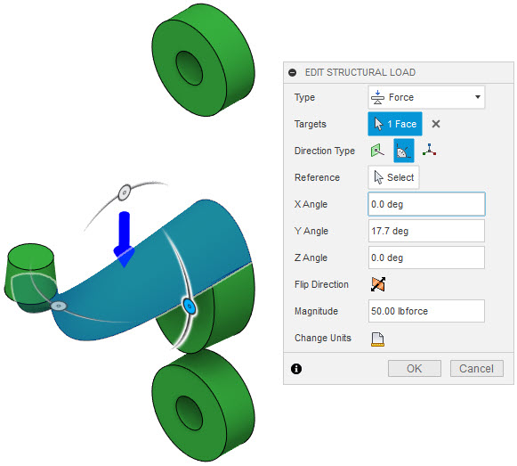
The Generative Study will need one or more load cases defined.  These contain structural loads and constraints that represent the forces that the part will encounter in the real world.  In this study, I have one Load Case.  My constraints are fixed constraints that will hold the part to the wall.  I have two loads, one of which is gravity.  The other is a static force on the surface that the bag will be hanging from.  Initially, I weighed my backpack to get the force accurate to reality.  I used 15 pounds.  My first few attempts to solve the study failed.  I realized that the force was too small for Fusion 360 to solve the study, so I upped the value to 50 pounds.  This will over-engineer the part but isn't necessarily a bad thing in this case.


 Manufacturing Methods
Generative Design is capable of creating parts with several different manufacturing methods in mind. The idea behind this project was to create something with Generative Design and follow it all the way through to a physical product.  With this product, I figured 3D printing or 3-axis milling would be the best methods.  I don't have access to either type of machine, however, I figured it would be easier to find someone to 3D print the part for me, so I chose that method.  There are a couple parameters that will be considered when using Additive.  We can evaluate different build directions as well as account for Overhang Angle and Minimum Wall Thickness.  When picking orientations, you need to consider the X, Y, and Z orientation of the model.  In my case, I used Y+ and Y- because the back face of my part is flat and is on the XZ plane.


 Materials
Since I chose 3D printing as the manufacturing method, I should pick a material that can be used in 3D printing.  PLA is one of the most common materials for 3D printing but is not in the Material library.  I could find the material properties of PLA and use those to define PLA in Fusion 360.  Another option would be to pick a different material.  ABS is part of the material library, so I chose to use that material for this study.


After all of the criteria are identified and entered, it is just a matter of solving the study.  Depending on how many Load Cases, Manufacturing Methods, and Materials I choose, Fusion 360 could take a couple hours to fully solve the study.  However, the software will display iterations of the solutions as they are completed.  In my case, it didn't take long to solve my Generative Study, since I only had one Load Case, one Manufacturing Method, and one Material.

As the results are displayed, you can look through the possible designs and different attributes of each.  As you find designs that you want to further evaluate, you can export them to their own design.  My first time through, I ended up getting this.


I realized that I over-designed the hook portion, which was identified as a preserve.  I decided to modify the preserved section of the hook and ended up getting this.


I think this came out looking pretty cool and  I am excited to get this 3D printed.  Check back here in a few weeks after I have a chance to get this printed because I plan on creating a post related to the 3D printing of this part.

If you want to see me walk through the design, here is a video that walks through the process.

Tuesday, December 15, 2020

Generative Design

The second half of this year has been pretty busy for me.  One area that I have invested a lot of my time has been learning Generative Design.  I still remember being at Autodesk University when Autodesk first started talking about this technology.  They had a bulkhead from an Airbus plane.  They talked about how much weight they were able to remove from just that one subassembly.  I knew then that this would be the future of design.

It has been a few years, but I have really had my first opportunity to really get into Fusion 360's Generative Design process and learn how to perform the design studies.  It really is a powerful technology and even though the studies are done in Fusion 360, I have sought ways to bring this ability to Inventor.  Through this learning and investigation, I have come to discover that Fusion 360's Generative Design process can be used on almost any file.  If you are using Fusion Team, you can use the Desktop Connector to sync your local files to the cloud.  Then use Fusion 360's Any CAD ability to place the Inventor model in a new Fusion 360 design.  If you can't leverage Any CAD, then you can always export and import an STP file.

Regardless of how you get your design into Fusion 360, either by designing right in Fusion 360, using Any CAD, or importing an STP file, you will need to do some sort of setup.  Generative Design has two key geometry definitions, Preserve Geometry and Obstacle Geometry.  Preserve Geometry is a body, or bodies, that need to be part of the final design.  They usually represent key connection points.  Obstacle Geometry is a body, or bodies, that need to be avoided in the final design.  Both of these can be component bodies or bodies modeled specifically for the design study.  You do have the option of creating a Starting Shape, which is a body that represents the shape you want to start with.  This is not a requirement and I don't often define a Starting Shape.


Preserve Geometry
 
Obstacle Geometry


The Connector Obstacle command does a great job of allowing you to define assembly hardware as obstacles.  You can pick a hole and define a bolt, with or without a nut, shown as cylinders.  You also can define a tool clearance, shown as another cylinder, which will ensure you have access to properly assemble your components.

Connector Obstacle

After you have all of the Preserves and Obstacles defined, you can begin defining your Load Cases.  Load Cases are Structural Loads and Constraints that represent different scenarios that your design is going to face.  You can apply static forces, pressure, moments, bearing loads, and remote forces, which were added in November of 2020.


Next comes defining your Objectives and Limits, this is where you can define the objectives for the study.  You have a few choices as to what types of outcomes you are looking for.  The most common is the Minimize Mass with a minimum Safety Factor.


One of the best parts of the Generative Design workflow in Fusion 360 is that it is manufacturing aware, meaning, that we can identify potential manufacturing methods and the study will take those into consideration when generating the outcomes.  We have choices of Unrestricted, meaning it will just generate the best shape possible, Additive, 2 1/2-Axis Milling, 3-Axis Milling, 5-Axis Milling, 2-Axis Cutting, and Die Casting.  Each will have its own specific parameters.  There is also the ability to enable cost estimation for the outcomes.  This enables you to enter the number of pieces you need to make and Fusion will use the aPriori database to also estimate manufacturing cost.


The last criteria you will have to define is the materials.  You can define the potential materials that are being considered for the component.  You can set materials for all manufacturing methods, or you set specific materials for specific manufacturing methods.


After all the setup, you can then Preview the outcome.  This is a good idea because it can help you see if you forgot to include a preserve or obstacle, which has happened to me once or twice.  


Then it is time to run the study.  The study will be done in the cloud.  When Autodesk first introduced this workflow, it cost 25 Cloud Credits to calculate the outcomes, however, they have since removed that cost.  Now the only cost associated with running the Generative Design Study is just a cost of 100 Cloud Credits per outcome that you generate an actual design file from.  The time it takes to fully calculate all the outcomes is a combination of how many manufacturing methods and materials you have chosen.  For me, it usually takes a couple of hours, but the actual time will vary.

As the study outcomes are being generated, you will be able to start looking at the results.  There are different display modes for the results and the left-hand side of the dialog gives you the ability to filter the outcomes of a variety of factors.  One of the newer enhancements is that you will receive recommendations as to which ones are seen as the best possible outcomes.


I could go on and on about filtering and sorting individual results, but the goal would be to export an outcome to a design file.  That would be better as another blog post soon, so this will all for now.  Hopefully, you will be able to leverage this workflow, regardless of which tool you use as your primary design tool.  

If you would like to see more, please watch my recent webinar on how to perform a Generative Design Study on an Inventor model.


Tuesday, November 3, 2020

Inventor Feature Properties

 Last week, I had a support call that the solution ended up being a familiar, yet relatively unused function of Inventor.  I had already been using Inventor for years before I found it and  I am not sure how many users even know about it.  I am talking about Conditional Suppression of the Feature Properties.  

Inventor Feature Properties users access to several different properties of a given feature in the browser.  It will allow a user to change the name of the feature, create some conditional suppression, enable or disable certain Adaptive elements, and change the appearance of the feature.

In this case, I want to focus on the conditional suppression options.  These allow a user to create conditional suppression of a feature based on the value of a parameter.  You might say, I can already do that with iLogic.  This is true, however, iLogic requires a certain level of comfort with writing VB.net code.  Inventor Feature Properties don't require any code and offer an alternative to users that are intimidated by iLogic.

The premise is really simple, you can access the dialog by right-clicking on a feature in the browser.


Once in the dialog, it is just a matter of defining the conditions of the suppression.  


The user can enable If then build and expression related to a parameter.  Your choices for parameters will be limited to any parameters of that feature and any parameter with a meaningful name.  Then it is a matter of picking the typical equation types, such as equals, does not equal, greater than, greater than or equal, less than, or less than or equal.  When it comes to the value to test for, it can be a static value or another parameter values.

Here is a simple demo video of how this can work.


This is a pretty simple command, but it is capable of quite a lot.  It is just a matter of identifying driving relationships.  At my job, we get a lot of requests from our customers to help them add automation to their designs.  We will typically lean on iLogic for that automation, but before we do, we consider if something like the Feature Properties can help us accomplish the given task before we jump to iLogic.  So think of the Feature Properties the next time you need to create some conditional suppression.


Thursday, October 22, 2020

Bringing a Little It's A CAD World to Autodesk University

 Every year Autodesk conducts Autodesk University or AU at locations all over the world.  It is the opportunity for Autodesk software users, industry experts, and Autodesk employees to gather together to share knowledge.  This year, in light of COVID-19, Autodesk has elected to host one virtual global event, which will be held November 17th to 20th.  Whether you have attended AU multiple times, or never attended, this is a great opportunity to grow your skills and knowledge.

You can still register for AU.

https://www.autodesk.com/autodesk-university/conference/overview

I have spoken at AU Las Vegas on a few occasions and since this year is being conducted virtually, I figured I would submit a few class proposals.  Two of those proposals have been accepted.  My class presentations will be pre-recorded next week, then I will be hosting a live Q & A for each of my two classes during the week of AU. 

The classes I will be teaching at AU are Vault & Inventor Properties:  Working Together for Better Data Management and The Essential Skills for Sheet Metal Modeling in Fusion 360.

Vault & Inventor Properties:  Working Together for Better Data Management is an in-depth look at the Inventor iProperties and Vault Property systems.  I will be discussing the differences between the two systems.  Then I will show how to create properties and mappings between the two systems to create a seamless experience for end-users.

The Essential Skills for Sheet Metal Modeling in Fusion 360 will cover the basic skills necessary for creating sheet metal models in Fusion 360.  I see a lot of posts in the Fusion 360 Facebook User Group from people that are looking for resources on how to get started in different areas of Fusion 360.  I felt that this class would be the perfect opportunity to create a resource for sheet metal modeling.  I will discuss the purpose of the Sheet Metal Rules and how the Flange command can be used to create three different types of geometry.

You can find these two classes and many more in the AU Session Schedule.

https://www.autodesk.com/autodesk-university/conference/schedule

If you do have the opportunity to attend, I hope you check out my classes and attend the live Q and A session for one, or both, of the classes.  It would be a great way to connect to those of you that have been reading this blog over the last few years.


Hope to talk to you then.


Thursday, June 25, 2020

Inserting Parameter Values into Drawing Text

The last parameter workflow that I wanted to share is how to insert a model parameter into a drawing note.  It is a feature I rarely use, but I don't do production work full-time.  The process is pretty simple but will link the value from the model to the drawing note text.  You will be at your most productive when you can create these types of relationships which cause Inventor to do the bulk of your time-consuming tasks.

To illustrate this, I thought about scenarios where drawings have notes about unmarked fillet radii.  This is where filleted edges are not dimensioned but the user will place a note that reads, "All unmarked fillets to be 1/16 in."  To make that note more intelligent, I could create a user parameter named FilletRadius, then use that parameter when creating the required fillets.  When I add the note on the drawing, I could insert the FilletRadius parameter's value into my note, instead of typing that value out.  Which would save me from having to edit the note if the FilletRadius value changes.

So the first step would be to create the necessary Model or User parameter.  For my example, I am going to create one called FilletRadius.


Then I need to create the Fillet features that use that value as the radius value.


The last step would be in the drawing file.  You start a Text Annotation as usual and type and static text that you need in the note.  For my example, I would type, "Unmarked radii have a radius of."  To get the User Parameter into the annotation, I configure the drop-down menus above the text pane.  Selecting the file, User or Model parameter, the required parameter, and the precision.  After those selections are correct, you can click on Insert Parameter, which will insert the specified value into the note text.  Then you can finish the note off with any other static text.


Here is a video demonstration of how to insert the parameter.


That is all there is to it.  Again, this creates a dynamic link between the model parameter and the text note.  This will eliminate having to update the model value and the note text if the unmarked fillet radii change.  The scenarios of where this can be useful are numerous.  Hopefully, you can use this technique to build similar relationships between model parameters and text notes.


Thursday, June 4, 2020

Automation Through Linked Inventor Parameters

Building automation into Inventor models is one of the biggest requests that I hear in my job.  Customers have a few projects that they have built and they want to find a way to leverage that and build new projects faster.  In most cases, the designs have variations in them that make them unique.  When I review these customer models, looking for ways to add automation to them, I first look for ways to utilize basic Inventor functionality before considering custom programing.  One of the easiest ways to get automation into a design or project is to link parameters.  

A model's parameters can be linked to either another model or an Excel file.  Once the parameters are linked, changing the values in one location will cause the linked parameter in all the other locations to update.  In most cases, the local update icon will light up in the other files, letting you know that Inventor sees new values and wants to update the models to reflect the new values.  The process of creating the link is pretty simple but can be very powerful and save time for the user and eliminate mistakes.

To link parameters to an Inventor file or Excel file, you will first need to open the Parameter dialog box and click the "Link" button.  


Inventor will then display the Open dialog, where the user can filter based on the file type they are looking for.  


If an Inventor model is picked, a dialog box will be displayed asking which parameters you would like to link.  


If the selected parameters are not marked for Export, Inventor will ask if it is okay to mark it for export.


Once that is done, Inventor will bring all the parameters into the parameter list.  


If an Excel file is picked, the user can also pick the Start Cell for where Inventor should start reading parameter values. 


Then Inventor will add the parameters to the list.


Here is a video demonstrating the process of linking parameters between Inventor files.


Here is a video demonstrating the process of linking parameters to an Excel file.


Having done this multiple times, I have a few tips that will save you from errors and make the process more manageable.  First of all, even though you can link parameters between models, Inventor will complain about a cyclical reference if you link parameters between an assembly and one of its parts.


If you prefer to control parameters by linking between Inventor files, you could create a separate file that holds all the parameters and then link the models to that file, as a shared resource. 

If you want to link parameters to an Excel file, you have to put all the values on the first tab in the file.  I have seen customers create multiple tabs for different calculations, then push those values to the main tab.  Also, when you link the parameters to an Excel file, you will be asked for a start cell.  Inventor will then start reading that column for parameter names and use the next cell to the right as the value.  If it sees a blank row, it will stop reading values.  By using different Start Cells and blank rows, you will have better control of which parameter values get pulled into which files.  One limitation of this is that you will not be to link one part file to a specific Excel file more than once. 

Lastly, I advise you to keep the parameter names of each file unique.  If you link in a parameter named "Length" and you already have a parameter named "Length" in your file, Inventor will change the name of the linked parameter to "Length_1."  I haven't seen this cause an error or issue, but it might cause confusion.

So that is all there is to it.  Using the ability to link parameters to other models or Excel files should give you an easy way to add some automation to your new or existing project.