Thursday, March 2, 2017

iLogic: Driving the Model from the Drawing

I was teaching a class the other day when a student posed an interesting question.  He wanted to know if there was a way to drive an Inventor model from the drawing.  In the workflow he was trying to create, a sales person could generate proposal drawings by entering the needed parameters.  This way the user didn't even have to open the model.

I thought about ways to make that happen and iLogic seemed to be the easiest solution.    I was not 100% certain that I could get the drawing to update properly when the parameters were passed, so I wanted to test.  While testing, I found a way around that if the model does not cooperate.

The setup is simple.  You create a part or assembly that is driven by parameters, a typical iLogic workflow.  You then just need to create the same parameters in the drawing.  Then you can create a rule that passes the parameters between the drawing and the model.

Here is some sample code:

modelName = IO.Path.GetFileName(ThisDrawing.ModelDocument.FullFileName)

Parameter(modelName & ".RailLength")= RailLength
Parameter(modelName & ".RailHeight") = RailHeight
Parameter(modelName & ".Color") = Color
Parameter(modelName & ".NoIntermediatePosts") = NumberOfPosts

iLogicVb.RunRule(modelName, "Update")

The first line finds the oldest view on the drawing and grabs the name of the model represented in that view.  This becomes important when using Copy Design, Replace Model Reference, or some other method that might change the model referenced in the view.  The file name is how the model is listed in the browser, which is how iLogic identifies the model.  The next four lines pass the drawing parameters to the model.

The last line is a way to get the model to update, if it does not automatically update.  It is a way of running a rule in the model that is there solely for the purpose of updating the model.

Here is a Screencast video where I show how this works on a sample model.


I will state that I was verifying this on several models.  I found that models that were using a component from the Frame Generator seemed to not update automatically, and didn't always respond to the extra rule that forced the update.  So any model that is using a Frame Generated component may need some extra effort to get updated.  I still have not found a foolproof way to accomplish the needed updates. 

Monday, February 13, 2017

VR for Total Beginners

I still remember when Virtual Reality (VR) became a big deal in the 1990s.  It's kind of funny how it seemed to go away for a while.  There really wasn't much talk about it in the early 2000s.  However, it seems to be back, and is a quickly growing technology.  I am not 100% sure why VR is making this strong comeback, perhaps it has something to do with accessibility though products like Google Cardboard.

There is so much talk about VR in world of CAD, and it is a little intimidating to try to figure out how to get started.  For years, rendering a CAD model in Inventor Studio, Showcase, or 3DS Max was the end goal for getting a rendering for customer presentations, web sites, etc.  However, I am seeing a push to VR for customer presentations and renderings.  Autodesk makes products like VRED and Stingray that enable users to create high-end VR experiences.  Those are both great products with a lot of great capabilities.  However, both require time and effort to learn.

Over the last few months, I have learned to create Stereo Panoramas using a variety of models from Autodesk software, such as Inventor, Fusion 360, Revit, and InfraWorks 360.  I would classify Stereo Panoramas as entry level VR.  They are immersive and require very little effort beyond the 3D model that you already have.  However, they do have their limitations, such as, they are a static image and offer no interaction with the model.

Depending on the product your 3D model was created in, you will have different ways to create a stereo panorama.  If you created a 3D model in Revit, AutoCAD, or Fusion 360, you can create views of the models, or cameras, then you can reprocess the render in the cloud as a stereo panorama.  If you are modeling in Inventor, InfraWorks 360, or other Autodesk product.  Your model can be Appended to a Navisworks model.  From Navisworks, you will be able to render your model in the cloud as a stereo panorama.

Here is the workflow for Inventor


Here is the workflow for InfraWorks 360


Here is the workflow for Revit


If the purpose of the render is to share the model with potential customers, a QR code can be generated, which will allow them to view the stereo panorama on their cell phone, with the help of Google Cardboard type device.  In a competitive environment, offering this type of conceptual model can be a key differentiator.

Here is how to share rendered Stereo Panoramas

Here are some samples of Stereo Panoramas from various Autodesk products.


Wednesday, January 4, 2017

As-Built Verification with ReCap 360

Some months ago, MESA was asked to do some as-built drawings for a customer that had us do the original assembly modeling in Inventor.  I saw this as a great opportunity to bring together the original model with a ReCap point cloud.  Through the process, I learned a few valuable lessons about the process and feel this is a good opportunity to share those lessons.

The first step in the process was to take the photos of the equipment.  From all my previous work with ReCap I knew that we wanted to take pictures from around the model, making a ring around the equipment, and pictures from different elevations.  One of my co-workers, Mike has a nice camera, so we got a ladder and started photographing the model.  We knew that ReCap has a limitation of 250 photos per model, and by chance, Mike took exactly 250 photos.

I took the photos and began creating the model.  I used a few measurements to ensure that the model would be scaled properly.  Looking at the point cloud from my first attempt, I was surprised that it seemed to have an issue with the back of the machine.  After thinking about it for a while, I realized why.  The decal on the front and back of the tank are the same, and since the tank is symmetrical, ReCap interpreted some of the photos of the back of the tank as being from the front.

My remedy to this was to split the photos into two groups, Group #1 was photos from the front and the two ends.  Group #2 was photos of the back and two ends.  So, then I was able to create point clouds for both portions of the equipment.  At that point, I had two options, create one ReCap project bringing in both the front and back point clouds, or bring both into the Inventor model.  I chose to bring them both into ReCap because that gave me the ability to create regions of points, which can be used to turn off unnecessary points.

Once all of that was done, I was ready to bring the point cloud into an Inventor assembly I created for the purpose of comparing the Inventor model to the point cloud.  I discovered something when I did this that I did not anticipate.  Even though, I had the model scaled properly and had the origin where I wanted, my point cloud was not flush to the origin the way I had hoped.  There are ways to tweak the point clouds orientation in Inventor, but the method of doing this was tedious to say the least.  I could perform some measurements to see how many degrees I needed to rotate the point cloud around its origin, then repeat for another axis, only to find that the previous axis would need adjusted.

The solution to this was to take better control of the orientation of the point cloud when registering points in the photos.  Instead of just assigning an origin point, I could give coordinates to the four corners of the equipment.  Doing this will improve the orientation of the point cloud and provide the scaling information for the point cloud as well.

With all of these lessons learned, I was able to develop a good workflow for bringing all of this together.

 Here is a Screencast that shows how to register the photos with the coordinate points.


Here is a Screencast that shows how to use Regions to clean up the data before bringing it into Inventor.


Here is a Screencast that shows how to bring the Inventor model together with the point cloud.


The workflow to perform the As-Built verification is not difficult, but if you follow this process, it will become easier.


Monday, December 19, 2016

Inventor Guided Tutorials

Over the last couple of years, Autodesk has initiated a move to slow down in-house training and support content and began encouraging users help their fellow users.  The Discussion Forums have been around for a really long time, and will always be a great way to get help.  A few years ago, Autodesk launched Screencast.  I describe Screencast as Autodesk's version of YouTube.  They then created the Autodesk Knowledge Network, by merging the forums with Screencast and adding the ability for users to write articles of their own.  With the release of Inventor 2017.3, Autodesk added another tool to that toolbox.  In Inventor 2017.3 users can now create their own guided tutorials.  


As an instructor, I immediately saw this as great way to transfer knowledge.  I just created my first Guided Tutorial, and it couldn't be easier. To be honest, previous versions of Inventor could do this, but it wasn't easy.  Autodesk knew how difficult it was, and have done a great job at making the process easy.


The process really starts outside of the software, with a planning stage.  It really is important to have a plan, or script.  I scripted out what steps a user would have to take to model the part in question.  That is important because the tutorial will be divided into Tasks, then into Steps.  Each task can have an overview Screencast attached. So my next phase was to record the Screencast videos for each Task.  It is worth noting that the tutorials look for a local WEBM file, so you will have to download the Screencast after recording them.  

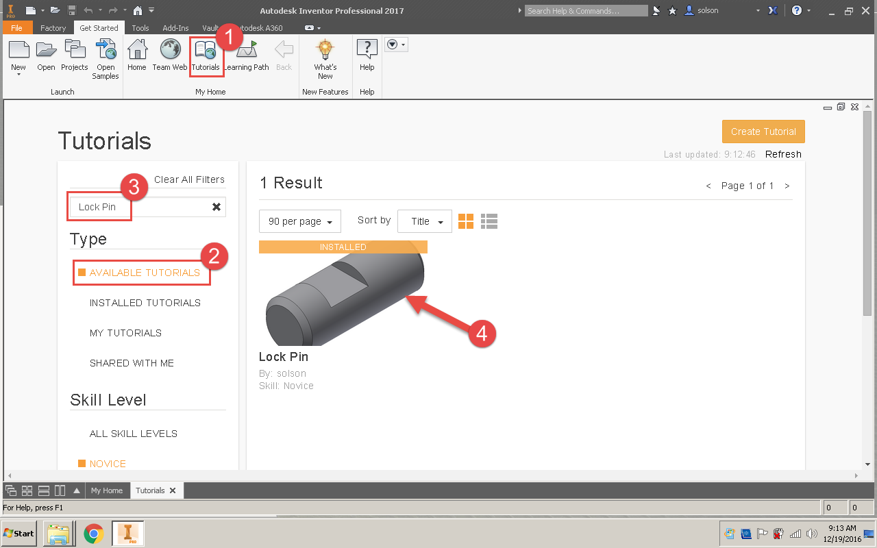
After the planning and creating the Screencasts, it was time to dive into Inventor to create the tutorial. It is a very simple to create the Tasks and break them down into steps. I like how I can associate commands to each step, so if a user is not sure what to do next they can be prompted with highlighted commands. Each Task can have a starting file, which is helpful if users join a tutorial after a Task or two. This files can be uploaded, or Inventor can capture the file that is the current model in Inventor. I have not tried enough of these to say which is best. I think it is great that you can capture the current model, but I have a feeling that I will eventually transition to having a saved file for each Task to upload.

Once the tutorial is created, it can be shared publicly or privately, through A360. I shared my first effort publicly. Search for my tutorial by going to the tutorial page, inside Inventor 2016 or 2017, and search for "Lock Pin."


Autodesk continues to give users great ways to help the larger community of users around them. The Guided Tutorials are another great way to do this. I think it is a great training option whether that is training in general or for a company specific workflow. So I urge you to check them out.

Monday, October 31, 2016

CAD with a Dad

I have been fortunate recently, my company has been willing to allow me to take time out of my work day to teach Fusion 360 to the homeschool co-op my children attend.  I had one hour, once a week, over 8 week to work with 10 kids that are between 10 and 13 years old.  This has been great for me and the kids in many ways.

First, I am pretty passionate about STEM education.  As a parent of three kids, I recognize that careers in STEM fields are a great path to success for them, knowing that some of the students are destined for other career paths.  Since Fusion 360 is 3D modeling, I see that this experience is a good place for the students to get their first connection with 3D modeling.  Whether they want to go into mechanical design and engineering, or 3D animation, the skills they learn in this class is going to lay the groundwork for the skills they will develop for those careers.

For me one of the greatest moments is to see my 12 year old son help his classmates.  I  started teaching him Inventor a couple years ago.  Grand total he has about 10 to 20 hours of instruction, and about another 10 to 20 hours of just letting him play in the software.  The first week of class was a tough class because nearly half the class needed additional one-on-one help to complete the exercise.  After a few minutes of helping each student out, I looked at my son and told him to see if he could help the other students that still needed help.  He was able to help a lot of students.  He got a great confidence boost to be able to help his classmates.  So beyond the CAD experience he gained, he gained experience as an instructor.  I was very proud to see that he still possessed the skills that he and I worked on previously.  He has told me on countless occasions that he wants to do what I do, and having this experience definitely reinforces that feeling.

This opportunity has also allowed me to share my knowledge, which is something I love to do.  I have built up a wide variety knowledge over the years, and I enjoy sharing it with the people I come in contact with.  The students I have in class have been very eager to learn Fusion 360.  It was great to seek the spark during one specific class.  I was showing them how to create 2D drawings from their 3D models.  I realized that this is not something they need to know a lot about, so I took some time and showed them reality capture and virtual reality.  That really seemed to grab their attention.

Most of the class was really excited to hear how ReCap 360 could be used to take pictures and turn it into a 3D model.  My desktop is a screenshot I took from a point cloud I made in ReCap 360 of a Lego Star War ship my son put together.  People always recognize the model and ask about it.  The students were amazed at what I was showing them.  Then, progressed to show them that some models can be rendered into a stereo panorama.  That stereo panorama could then be viewed in an app that would immerse the viewer in the model.  That really got them excited to what we were talking about.

I don't know if any of them will go on to careers in science, technology, or computer animation, but I feel great about being able to help them take the first step down that path.

Here is a slideshow highlighting work that they did on their own, without direction, following their own inspiration.


Monday, September 19, 2016

Factory Scope v. Member Scope

iParts and iAssemblies in Inventor are a great way to create a collection of parts or assemblies that are similar but have a certain amount of uniqueness.  I have created several videos that demonstrate how to create and work with iParts.  One topic that I have not mentioned before is Factory Scope v. Member Scope.  I think this is information can be very valuable when working with iParts and iAssemblies.

Recently, I was working with a customer while he was adding a member to an iPart.  He continually jumped between sketches and feature and the iPart table.  We was checking the names and values of dimensions, then going to the table and changing the value for the new member.  After doing that a few times, he asked me, "Is there any way I can change the values in the model without having to go to the table?"

To which I replied that there was.  I pointed him to the Factory Scope/Member Scope setting.  For users that are not familiar with the purpose of this setting, it allows a user to specify if a change is for the entire factory(all members) or for a specific member.  By default Inventor is set to Factory Scope, that means as the user changes the model, those changes are applied to all members.  If the user changes that setting to Member Scope, the edits that the user performs are applied only to the active member of the iPart family.

Member Scope works great for editing the parameters already on the table, but also can be helpful when controlling feature suppression.  You are allowing Inventor to control and edit the table for you as you make changes.  It is really interesting to see the impact on the table as features are added while in Member Scope.  All the user has to do is add the necessary feature(s) and Inventor will handle adding the parameters and feature controls to the table.

Here is a Screencast that demonstrates the Power of Member Scope:

Tuesday, August 16, 2016

Configuration in the Hands of Your Customers

Autodesk has such a big library of products, it is difficult to keep tabs on all the products and what they do.  When I first saw Configurator 360 at AU several years ago, I was impressed.  At the time the product was new and Autodesk has developed the product significantly since its introduction.  I think it is a great product and can be useful to a lot of companies, so I have been spreading the word about Configurator 360.


Configurator 360 allows Inventor users to upload configurable models to a web site.  That web site can then be shared with customers or sales staff.  Customers then can customize the model and download their model and request a quote for it.  The main types of models that users upload are designs with iLogic Rules, but the model can be just a parameter driven part.  


The Configurator 360 site administrator can control a wide variety of preferences for all models or specific to designs.  For example, customers can download their customized design in a variety of formats, everything from STEP and IGES to Catia and Revit files, along with the native Inventor model.  The site administrator can pick and choose which file formats users are permitted to download.  I strongly recommend disabling the Inventor download because those files will contain the intellectual property of your company.  However, I have set as a possible download on my demo site, just to show the exhaustive list of downloads.

Here is a video I made that gives an overview of the Inventor to Configurator 360 workflow.


Here is a line to a design that I typically use as a sample for iLogic and Configurator 360


Autodesk has done a lot of development around the quoting capabilities of Configurator 360.  They have made incremental changes along the way.  Now, users are able to upload a quote template, complete with images of the customized design.


One of my favorite functions of Configurator 360 is the Accessories.  This allows users to author components as optional accessories.  The process starts in Inventor by creating a Joint between the main design and the optional component.  The Configurator 360 Add-in for Inventor will help split the Joint definition to the two models.  After both are uploaded, users can drag and drop the accessories on to the design, and the Joint definition will place the optional component on the assembly.

This link is to a design that includes accessories.

If you are selling customizable products Configurator 360 would be a great addition to your CAD tools.