Accessing a model's parameters in Inventor gives a user access to many functions. You probably have changed values directly in the Parameter dialog. Perhaps you have even given the parameters descriptive names or created equations between values. However, there are several functions that are available that are often overlooked.
Did you know that you can have iProperties pull parameter values? Did you know that you can link parameters to Excel files or other Inventor models? You can even pull parameters into text notes in an Inventor drawing. Leveraging these functions can simplify your daily workload, so I wanted to share some of these often-overlooked parameter functions. So in the coming weeks, I will be sharing blog posts and videos on how to incorporate these into normal workflows. First up, will be how to pull parameter values into iProperties. Come back next week and check that out.
Thursday, April 30, 2020

Wednesday, April 8, 2020
Fusion 360: Rest Machining Between Setups
If you consistently read my blog, it doesn't take long to notice that there is a large cross-section of material covered. That is influenced by my job, but it is also related to my drive to constantly learn new skills. Similarly, Autodesk keeps expanding its offering, and one of their current areas of development is CAM. Consequently, I have been spending some of my time picking up some CAM skills. Recently, I was talking to one of our customers that does CNC machining. He had an interesting question that lead me to a really cool workflow that I thought was worth sharing.
The Scenario:
The customer had a part that required machining on more than one side. Also, he preferred to include the vise in the model to make sure he didn't have any issues with the tool contacting his workholding. He wasn't exactly sure how to approach the multiple setups, but his biggest question was how could he get the stock for the Setup 2 to be the shape that was left after the operations of Setup 1.
The Answer:
I knew Fusion 360 was capable of all of this, but it had been a long time since I had worked with Fusion 360's ability to export a setup's remaining stock. Also, Fusion 360 had changed so much since the last time I had done it and I wasn't confident that it worked the same way, as the last time I used it. So I had to do a little bit of research to refresh my memory.
During my research, I found two important pieces of information. First, a reminder for where the command was to export stock from a setup. Secondly, there was a feature preview that allows a user to use the previous setup's remaining stock as the stock for a setup. However, I tried this a few times and I was never able to get it to work. It is only a preview feature and that typically means that Autodesk is not quite done with it. So I wasn't too disappointed.
The first part of what this user was trying to do was easy. Fusion 360 allows for multiple setups with different coordinate systems, fixture identification, and stock definitions. The coordinate system is the critical part because the tool for milling operations always comes from the Z-axis.


The Scenario:
The customer had a part that required machining on more than one side. Also, he preferred to include the vise in the model to make sure he didn't have any issues with the tool contacting his workholding. He wasn't exactly sure how to approach the multiple setups, but his biggest question was how could he get the stock for the Setup 2 to be the shape that was left after the operations of Setup 1.
The Answer:
I knew Fusion 360 was capable of all of this, but it had been a long time since I had worked with Fusion 360's ability to export a setup's remaining stock. Also, Fusion 360 had changed so much since the last time I had done it and I wasn't confident that it worked the same way, as the last time I used it. So I had to do a little bit of research to refresh my memory.
During my research, I found two important pieces of information. First, a reminder for where the command was to export stock from a setup. Secondly, there was a feature preview that allows a user to use the previous setup's remaining stock as the stock for a setup. However, I tried this a few times and I was never able to get it to work. It is only a preview feature and that typically means that Autodesk is not quite done with it. So I wasn't too disappointed.
The first part of what this user was trying to do was easy. Fusion 360 allows for multiple setups with different coordinate systems, fixture identification, and stock definitions. The coordinate system is the critical part because the tool for milling operations always comes from the Z-axis.

The vise portion of the workflow isn't difficult either, it is possible to have multiple instances of the same vise in the model. Then it is just a matter of using the necessary Joint definition to orient each vise appropriately. Then the user can toggle the visibility of the vises as needed.
When it comes to the initial CAM setup, if you are going to place and constrain your part in a workholding, you will also need to model the stock for Setup 1 as a body or component. This is because you will need selectable geometry for the Joint between the stock and vise. The stock generated by the software for the setup will only be seen while you are in the Manufacture workspace, where you will be unable to make the joint. I will admit it is possible to create offsets in the joint to get the jaws to the necessary positions. However, that creates a disconnect between the defined stock and the jaw placements.
 |
| Setup 1 |
 |
| Setup 2 |
The process of getting the result of one setup to be the stock for another setup is not that complicated. However, if you plan on including your workholding, there are some intricacies that you will need to account for. The process of exporting the solid is just a matter of simulating the setup, then playing the complete simulation or jumping to the end. Then the command to save the stock is in the right-click menu.

The remaining stock will be saved as an STL file on your local machine. At this point, it could be brought back into the same design file. The one exception to this is if you want to place it in a vise. This is because the STL is a mesh file and in my testing, I was unable to select the mesh faces and edges while defining the joint to place the stock in the vise.
It is possible to convert the mesh into a solid, but that is best done in a separate file. For the Mesh to Brep command to be available, you have to disable the setting for Capture Design History. So my process in this case is:
- Start a new design file
- Insert mesh file, scaling if necessary
- Disable setting for Capture Design History
- Use Mesh to BRep to convert the mesh to a solid model
- Save the design
- Return to original design
- Place and ground the stock for the next setup
Because the origin of the original design and the imported mesh are the same, it worked out that the new stock landed on the original model. This may not be the case for you so you might want to check this and move bodies as needed.
The last step in the process above is to ground the stock. The reason for that is when you create the joints to hold the stock in the vise, the stock is likely to move away from the original design. This is not ideal and the easiest fix is to just ground the newly imported stock.
At this point, the new stock should be located over the original model, and you may or may not have it placed in a vise. Now you can return to the Manufacture workspace and begin creating your new setup. This time, when picking stock, you will use the From Solid option and pick the imported stock model. I like to do this by picking it from the browser, that way I don't get the wrong body, especially because the model and the stock are overlapping.

Then you should return to the Setup tab to define a coordinate system that matches the part origin and orientation for this setup.

I do want to remind you that this is an export and import process. So if the operations in Setup 1 change enough that the remaining stock will change, you will need to perform the export and import processes again.
Here is a YouTube video that demonstrates the process.
I don't CNC program for a living, but I feel pretty confident that this would be my process if I did. I think this process gives you a truer representation of what is happening and will likely lead to more efficient programs.
Tuesday, March 31, 2020
Inserting Properties into an Inventor Title Block
This is my last post in my series covering Vault Properties and Inventor iProperties. I have previously explained that there is a difference between Vault Properties and Inventor iProperties. Then the last two posts have been instructions on how to create the property in Vault and map properties to Inventor custom iProperties. Once you have those properties created and mapped, what can we do with those properties? They can be shown on drawings in Parts Lists, Title Blocks, and Borders. So I wanted to complete the series by explaining how to get these properties onto a drawing.
Placing properties on a title block isn't that difficult, but if you haven't done it before, you may not know where to start. Also, custom iProperties are a little bit tricky. For the purpose of explaining how to do this, I am going to say that I want to add Stock Location and Originator to my title block and I want to add Stock Location to my Parts List. That way someone in the warehouse can look at the drawing and know where to find the parts.
Since this is something that we want on all of our drawings, I am going to edit my drawing template. I will need to have a model that already has those iProperties. Then I will need to open my drawing template. To do this properly, you want to use File> Open to open your template. You don't want to go to File> New. Once the template is opened, you need to add a base view of a model that contains those custom iProperties. It doesn't really matter what the model is because we will delete the view once we have placed its properties in the title block.


Placing properties on a title block isn't that difficult, but if you haven't done it before, you may not know where to start. Also, custom iProperties are a little bit tricky. For the purpose of explaining how to do this, I am going to say that I want to add Stock Location and Originator to my title block and I want to add Stock Location to my Parts List. That way someone in the warehouse can look at the drawing and know where to find the parts.
Since this is something that we want on all of our drawings, I am going to edit my drawing template. I will need to have a model that already has those iProperties. Then I will need to open my drawing template. To do this properly, you want to use File> Open to open your template. You don't want to go to File> New. Once the template is opened, you need to add a base view of a model that contains those custom iProperties. It doesn't really matter what the model is because we will delete the view once we have placed its properties in the title block.

So the next step would be to edit the title block. You can right-click on the title block on the active sheet, in the browser, or on a title block listed under the Drawing Resources. Then click Edit Definition.

This will open the sketch of the title block. It can be a little overwhelming because you are going to see dimensions, names of properties that populate the title block and labels for those fields. Most often these will run together and make it a little hard to read. However, zooming in on certain sections will help.

In this example, I am using the default Inventor Title Block. So, I think I will change QA to Originator, then place the Originator property in that block. Then I will add Stock Location at the bottom of that column. So first I will double-click on QA to change the text of that label to Originator. Then, I can use the Text command to add a place holder for this property into the title block sketch. To get the custom iProperty into the place holder, you will need to use the drop-down boxes above the text window to pick the right iProperty type\source, then the desired property. Then clicking the "x" symbol will place that property into the text window.

After the text is placed, you can control the position of the text, in relation to the insertion point, through the two sets of justification toggles.
Then at the sketch level, the insertion point can be constrained or dimensioned to locate it properly.

So now, I am going to insert a text label, using the text command to label the last box Stock Location. Then, I will insert the Stock Location custom iProperty into that box. The following image is what it should look like when done.

When you are done editing your title block sketch, you can click Finish Sketch to exit sketch mode. Inventor will ask if you want to save the edits or if you want to do a Save As. In my example, I will just save it.

Here is a YouTube video that shows how to make these changes to the title block.
Adding Stock Location to the Part List is pretty simple, but there is a wrinkle that makes it more difficult. The issue is that Parts Lists are style based, which means it pulls definitions from the Style Library. So I could modify the Parts List Style in the template, but if I don't add it to the Style Library, I could have the change undone by the Style Library.
Before changing the Parts List style, you will need to make sure that your Inventor Project has Use Style Library set to Read-Write.

I typically tell users that this setting should be set to Read-Only because I don't want users inadvertently making changes to their styles. To change this from Read-Only to Read-Write, you will have to make sure all of your Inventor files are closed and if you are using Vault, the project will have to be checked out to you.
After you have made that change, you can open the drawing template and navigate to the Style Editor.

Under Parts Lists, you will see all the Part List definitions in this template and the Style Library. You are most likely using one customized to your company. I am using the default template in this case. So I will just copy one of the default styles because I don't like modifying the default styles. I am going to select Parts List (ANSI) and click New at the top. This will copy Parts List (ANSI) and ask me to name the new style.
To add the custom iProperty, I will have to click on the Column Chooser, then select New Property. Then I can click where it says <<Click here to add a new property>>. Then I can type Stock Location, which is the name of the custom iProperty I want to add. This will be case sensitive, so make sure to type it so it matches the way it was spelled in the other places it was used.


Then back in the Column Chooser dialog, the columns can be ordered using Move Up or Move Down, which are under the selected properties.

Now the style will need to be saved, by clicking on Save at the top of the Style Editor.
So that added the column to the Parts List, but there is one other issue to consider. Is this Parts List going to be our main/default Parts List? If so, you will want to change this style to the default Parts List under the Object Defaults.

Doing this will make sure that Parts List w\Stock Location will be the default style for Parts Lists in the future.
Now we need to save these changes to our Style Library. That is done by using the Save command from the Styles and Standards panel of the ribbon.
This will compare styles in the drawing to styles in the Style Library and offer to change the Style Library's styles to match the ones in the drawing. This cannot be undone, so make sure you are ready to do this before clicking OK.

Once the styles are saved to the Style Library, don't forget to save the template and change your Inventor Project back to Use Style Library = Read-Only. If you are using Vault, you will want to undo your check out of that file.
Here is a YouTube video I made that demonstrates this process.
The process of adding the custom iProperty to the title block or parts lists are not too difficult. Making sure the Style Library is updated with the new Parts List style is probably the most difficult part. However, if you can get all your properties managed in your CAD files and in your Vault, you will have a lot easier time getting the right information to show up in the right places.
Friday, March 27, 2020
Mapping Vault Properties to Inventor iProperties
When I started this series about Vault Properties, I pointed out how there is a difference between Vault Properties and Inventor iProperties and I mentioned that it is possible to create a mapping between them. In my last post, I explained how to create a Vault Property because I felt that most users will have to create that property first. Primarily because most iProperties are already mapped to Vault.
So now that we understand that there is a difference and we have the necessary Vault Property, I want to explain how to create the mapping between our Vault Property and an Inventor iProperty. The only other prerequisite is that we have to have an Inventor file that has the desired iProperty, in most cases, this will be a Custom iProperty.
The example I use to demonstrate this is a property called Stock Location. It is the location in the warehouse that this part is stored. My Inventor file will have a custom iProperty named Stock Location and it will hold that value.


So now that we understand that there is a difference and we have the necessary Vault Property, I want to explain how to create the mapping between our Vault Property and an Inventor iProperty. The only other prerequisite is that we have to have an Inventor file that has the desired iProperty, in most cases, this will be a Custom iProperty.
The example I use to demonstrate this is a property called Stock Location. It is the location in the warehouse that this part is stored. My Inventor file will have a custom iProperty named Stock Location and it will hold that value.

As long as you have one Inventor file with that iProperty definition, you are ready to map it to your Vault Property. Go to Vault and open the Property Definition dialog, select the property you want to map to, and click Edit.

Then on the Mapping tab of the edit dialog, you will be able to click on "Click here to add a new mapping." This will enable a row for you to define the mapping, each of these fields is a drop-down menu. I always start with the Provider column. Clicking in that cell will show a drop-down of all the different types of providers available. In our case, we will pick Inventor (.ipt, *.iam, *.idw, *.ipn, *.ide). Please note the other possible selections as well.

Then you will need to designate the File Property. In this case, Vault will want a sample file that it will pull property definitions from. It is capable of pulling from the Vault or from a local file, so make sure to pick the proper option based on where the sample file is stored. Then click "Import Properties" and pick the proper option.
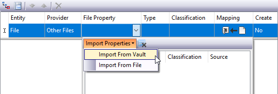
Then the user will be prompted to select the sample file and the File Property drop-down will be populated with all the properties defined in that file.

Then the user can select the desired property from the list. I do want to point out that Vault will retain that same list during this session of Vault, so if you want to map several properties to properties from the same sample file, you will only need to pick that sample file once. Also, if you pick a second sample file, this list will display both sets of properties. If this list gets too cumbersome because of adding several sample files, the icon next to "Import Properties" will clear the list.
There are two other options here that are good to understand. The Mapping will define if this is a bi-directional mapping or a one direction mapping. For a user-defined property, you will have several options. If you are mapping a Vault System Property to an iProperty, you will only be able to have Vault push its value to Inventor. This is because Vault System Properties are not editable by users. The "Create" option will tell Vault if it should create the property on the CAD file if it doesn't exist. Once all of the options have been selected and the user clicks out of that row, the mapping is defined and moved below the line in the Window.
It is possible to create multiple mappings on the same properties, if multiple mappings exist, it is possible to order, or prioritize them from greatest to least.

I will caution against creating too many mappings, I have talked to several customers recently that have cyclical, or conflicting, mappings and it resulted in undesired property behavior. So be careful when creating multiple mappings for the same property.
Also, just creating the mappings will not automatically cause the property to be populated with the data from the CAD file. Running a re-index on the Vault will prompt Vault to begin pulling the data from the mapped properties into the Vault database. If you don't perform a re-index, the mapping will be carried out as files are checked into the Vault.
Here is a YouTube video that shows the process.
That is all there is to it. Following these steps, you should be ready to start mapping all of your custom Inventor Properties to Vault Properties.
Thursday, March 26, 2020
Creating a Vault Property
Since Autodesk Vault is run on a SQL database, it is a very powerful tool for keeping track of CAD files and their associated data. The ability to search on the properties of Vault is one of the best ways to find and reuse designs. Even though Vault is loaded with a variety of existing properties, it may become necessary to create your own Vault Properties. So I wanted to dedicate one blog post, in this series about Vault Properties, to how to create a Vault Property. Before I get into the steps in the process, I want to remind you that only users with an Administrator role will be able to do this.
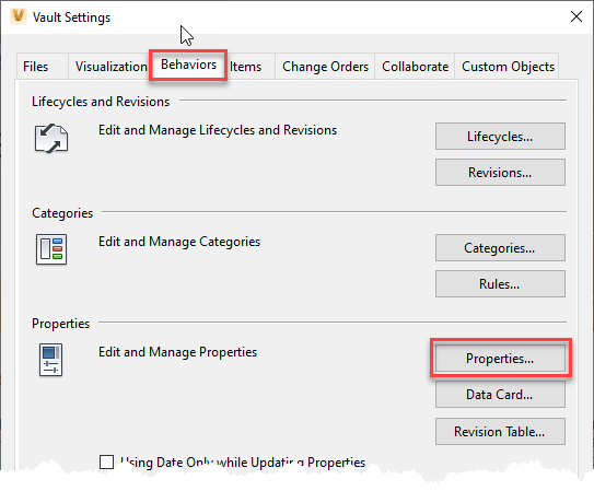
The first step is to open the Property Definitions dialog, which is located on the Behaviors tab of the Vault Settings dialog, which can be found by going to Tools> Administration> Vault Settings.


So with these steps, you should be able to create your own properties inside of Vault. Which will enable you to keep track of all the important information about your designs and related files. Some of this information will be best mapped to your CAD files. I intend to cover property mapping in my next blog post, so be sure to look for that post within the next week.
The first step is to open the Property Definitions dialog, which is located on the Behaviors tab of the Vault Settings dialog, which can be found by going to Tools> Administration> Vault Settings.

 |
| Property Definitions Dialog |
Once you are to the Property Definitions Dialog, it is just a matter of click on New and entering the desired information.

For the most part, some of these options are straight forward. For example, Name is the name of the property. As long as you are not using special characters or duplicating an existing property name, there shouldn't be any issues here. Type is just what type of data is going into this field. Is it text, a number, a date, or a true/false value?
The Associations are a little more in-depth. When it comes to Vault Basic, Vault Workgroup, or Vault Professional, there are different functions inside of Vault and the new property can be associated with any one of those objects. The Associations get into is this going to be a property for files, if so, which categories? Is the property going to be associated with Items, if so, what kinds? And so on.

After Associations, the user will need to define some of the specific settings for that property. One option is to have this property included when someone does a basic search. There are also additional options to set an initial value, force a list of values, require a value, etc. Each association can have these set independently from one another.
There is a tab for Mapping. This will allow users to create a mapping between the Vault Property and properties of the actual CAD files, such as Inventor's iProperties. Property Mapping should really be a post of its own. So I will cover that is my next post.
Here is a video demonstration that I have posted to YouTube.
Wednesday, March 25, 2020
Understanding Inventor's iProperties and Vault's Properties
In recent weeks, I have been finding that I have been talking to a lot of CAD managers and CAD users about the differences between the Inventor's iProperties and Vault's Properties. So I decided to kick off a short series of posts regarding properties.
Out of the box, Vault is set to map a lot of its properties to Inventor's iProperties, or vice versa. It does such a great job that users don't realize there is a difference.
To recognize the difference, it is important to understand how Vault it structured. Vault's information is split into two parts: the file store and the database. The file store is all of the files that are stored in the Vault. The database is a SQL database that stores all of the metadata of the files. Metadata is basically a fancy term for all of the properties of the files. So when a user is in Vault looking at all a particular folder, they can display a variety of properties. In this case, they are really looking at the properties in the database for those files. Again, most of Inventor's iProperties are already mapped to Vault Properties, so it gives the illusion that you are looking at the iProperties.

Vault actually has two types of properties, User Defined Properties (UDP) and System Properties. System Properties are attributes that Vault needs to keep track of, so you are not able to edit these. Some examples of System Properties are: Checked Out By, Date Version Created, and Revision, just to name a few.
Now a User Defined Property can be pretty much anything a user needs to track. Vault has a significant number of UDPs by default, but Vault Administrators can add as many properties as they need. These properties can also be editable.
Out of the box, Vault is set to map a lot of its properties to Inventor's iProperties, or vice versa. It does such a great job that users don't realize there is a difference.
To recognize the difference, it is important to understand how Vault it structured. Vault's information is split into two parts: the file store and the database. The file store is all of the files that are stored in the Vault. The database is a SQL database that stores all of the metadata of the files. Metadata is basically a fancy term for all of the properties of the files. So when a user is in Vault looking at all a particular folder, they can display a variety of properties. In this case, they are really looking at the properties in the database for those files. Again, most of Inventor's iProperties are already mapped to Vault Properties, so it gives the illusion that you are looking at the iProperties.

Vault actually has two types of properties, User Defined Properties (UDP) and System Properties. System Properties are attributes that Vault needs to keep track of, so you are not able to edit these. Some examples of System Properties are: Checked Out By, Date Version Created, and Revision, just to name a few.
 |
| Vault System Properties |
 |
| Vault User Defined Properties |
Now, Inventor's iProperties have essentially the same role. They are designed to allow users to track attributes of the design. Then they can be used to populate Bills of Material or Title Blocks. Just like Vault, they can be edited and users have the ability to create their own custom iProperties.
 |
| Inventor's iProperties |
The biggest take away here is to understand that there is a difference between the Inventor iProperites and Vault Properties. It is possible and some-what essential to map iProperties to Vault Properties to make use of Inventor and Vault easier. For this reason, Autodesk has set up default mappings between the most common Inventor iProperties and Vault Properties.
In future posts, I intend on covering how to create Vault Properties, how to create the mapping between a Vault Property and a custom Inventor iProperties, and how to add a custom iProperty to a Title Block.
Thursday, December 19, 2019
Connecting Drone Survey Data to Civil 3D and InfraWorks
In my previous blog post, I discussed how to use ReCap Photo to generate a 3D model from photos taken during a drone site survey. Just having the 3D model is not good enough, you need to be able to get it into your design tool, whether that is Civil 3D or InfraWorks. That is what I would like to cover in this post.
Once I learned that ReCap Photo was mesh-based, I began to wonder, "Are meshes better for use downstream?" I tried taking the mesh files into Civil 3D and InfraWorks to see how they worked. Based on that experience, I would say that RCS and RCP files, which are ReCap point clouds, are the better choice for output from ReCap Photo. That is why I will always choose for ReCap Photo to generate an RCS file when creating the project. It is not mandatory to create the RCM, but I typically do that out of habit.
Once the project is done calculating in the cloud, it can be downloaded. Hovering over the thumbnail for the project will allow you to download, or delete the model if necessary.

This will download a folder containing files and/or zip files of the output files that were chosen during project creation. If the goal is to take the model into Civil 3D or InfraWorks, the user can extract the data from the RCS.Zip file.

The next step is up to the individual user, you can go right into your design tool or go into ReCap to do some cleanup. If you take the RCP file into ReCap first, you can delete stray points or classify points into regions, such as site, building, trees. The benefit of regions is that they essentially become layers that can be turned off or on when you get into Civil 3D. Deleting points versus creating regions have their pros and cons and it is up to the end-user to decide which approach they would like to take. My personal preference is to take the output file into ReCap and create regions.
If you have chosen RCS as an output type, the download will contain a zip file with .RSC.Zip at the end. If you extract that files, you will find an RCP file, which can be opened in ReCap.

Once the model is opened, it is just a matter of selecting points and then deciding to either delete them, classify them into a region, or cropping based on the selection.

After any necessary cleanup, it is possible to insert this model into InfraWorks and Civil 3D.
In InfraWorks, the point cloud can be added to a model as a data source. From the Data Sources menu, you just have to select Point Cloud from the Add File Data Source drop-down.

Once the Point Cloud has been added, it will need to be configured. Since the point cloud should have the correct geolocation, it should land in the right spot. However, I have noticed that the elevation of the point cloud can be a little lower than it should be, so it may be necessary to tweak the Z offset.

Here is an up-close look at the model with the point cloud. You can see the building footprint brought in from OpenStreetMap, which can be deleted if necessary.

In Civil 3D, the workflow for connecting to a point cloud has not changed at all. There is one small difference though. In Civil 3D there has always been a command for attaching a point cloud. However, Autodesk has added RCP and RCS files as possible choices for the Attach command. In the end, regardless of which command you use, the workflow for point clouds is the same. You just have to select the point cloud file to attach, then you will have the ability to specify the insertion point, which I typically leave as 0, 0, 0 because the model should be properly geolocated by ReCap Photo. If you need to tweak the elevation, you can do that by changing the Z value for the insertion point.

A potential next step would be to create a surface from the point cloud. This tool has been around since AutoCAD Civil 3D 2015 as an extension tool, then was added to the standard tools inside of Civil 3D.

Using this tool, a user can create a surface from an entire point cloud or just selected points. The biggest element of this process is the filter settings. I always pick the Kringing method, just because it seems like the best option when compared to Planar Average and No Filter.


Once created the surface from the point cloud can be used just as any other Civil 3D surface.
Here is a video demonstration of the workflow for InfraWorks and Civil 3D.
Both of these workflows can be beneficial it is just a matter of which product you need to place your point cloud. When ReCap Photo was introduced, I was nervous that I lost part of a great workflow. It wasn't lost, it was just a matter of I didn't know how to access the point clouds that were generated by ReCap Photo. Once I found where to access them, I began to appreciate how simple it is to access them.
Once I learned that ReCap Photo was mesh-based, I began to wonder, "Are meshes better for use downstream?" I tried taking the mesh files into Civil 3D and InfraWorks to see how they worked. Based on that experience, I would say that RCS and RCP files, which are ReCap point clouds, are the better choice for output from ReCap Photo. That is why I will always choose for ReCap Photo to generate an RCS file when creating the project. It is not mandatory to create the RCM, but I typically do that out of habit.
Once the project is done calculating in the cloud, it can be downloaded. Hovering over the thumbnail for the project will allow you to download, or delete the model if necessary.


The next step is up to the individual user, you can go right into your design tool or go into ReCap to do some cleanup. If you take the RCP file into ReCap first, you can delete stray points or classify points into regions, such as site, building, trees. The benefit of regions is that they essentially become layers that can be turned off or on when you get into Civil 3D. Deleting points versus creating regions have their pros and cons and it is up to the end-user to decide which approach they would like to take. My personal preference is to take the output file into ReCap and create regions.
If you have chosen RCS as an output type, the download will contain a zip file with .RSC.Zip at the end. If you extract that files, you will find an RCP file, which can be opened in ReCap.

Once the model is opened, it is just a matter of selecting points and then deciding to either delete them, classify them into a region, or cropping based on the selection.

After any necessary cleanup, it is possible to insert this model into InfraWorks and Civil 3D.
In InfraWorks, the point cloud can be added to a model as a data source. From the Data Sources menu, you just have to select Point Cloud from the Add File Data Source drop-down.

Once the Point Cloud has been added, it will need to be configured. Since the point cloud should have the correct geolocation, it should land in the right spot. However, I have noticed that the elevation of the point cloud can be a little lower than it should be, so it may be necessary to tweak the Z offset.

Here is an up-close look at the model with the point cloud. You can see the building footprint brought in from OpenStreetMap, which can be deleted if necessary.

In Civil 3D, the workflow for connecting to a point cloud has not changed at all. There is one small difference though. In Civil 3D there has always been a command for attaching a point cloud. However, Autodesk has added RCP and RCS files as possible choices for the Attach command. In the end, regardless of which command you use, the workflow for point clouds is the same. You just have to select the point cloud file to attach, then you will have the ability to specify the insertion point, which I typically leave as 0, 0, 0 because the model should be properly geolocated by ReCap Photo. If you need to tweak the elevation, you can do that by changing the Z value for the insertion point.

A potential next step would be to create a surface from the point cloud. This tool has been around since AutoCAD Civil 3D 2015 as an extension tool, then was added to the standard tools inside of Civil 3D.

Using this tool, a user can create a surface from an entire point cloud or just selected points. The biggest element of this process is the filter settings. I always pick the Kringing method, just because it seems like the best option when compared to Planar Average and No Filter.

Here is an example of a surface I created from an attached point cloud.

Here is a video demonstration of the workflow for InfraWorks and Civil 3D.
Both of these workflows can be beneficial it is just a matter of which product you need to place your point cloud. When ReCap Photo was introduced, I was nervous that I lost part of a great workflow. It wasn't lost, it was just a matter of I didn't know how to access the point clouds that were generated by ReCap Photo. Once I found where to access them, I began to appreciate how simple it is to access them.
Subscribe to:
Posts (Atom)