Thursday, December 19, 2019

Connecting Drone Survey Data to Civil 3D and InfraWorks

In my previous blog post, I discussed how to use ReCap Photo to generate a 3D model from photos taken during a drone site survey.  Just having the 3D model is not good enough, you need to be able to get it into your design tool, whether that is Civil 3D or InfraWorks.  That is what I would like to cover in this post.

Once I learned that ReCap Photo was mesh-based, I began to wonder, "Are meshes better for use downstream?"  I tried taking the mesh files into Civil 3D and InfraWorks to see how they worked.  Based on that experience, I would say that RCS and RCP files, which are ReCap point clouds, are the better choice for output from ReCap Photo.  That is why I will always choose for ReCap Photo to generate an RCS file when creating the project.  It is not mandatory to create the RCM, but I typically do that out of habit.

Once the project is done calculating in the cloud, it can be downloaded.  Hovering over the thumbnail for the project will allow you to download, or delete the model if necessary.


This will download a folder containing files and/or zip files of the output files that were chosen during project creation.  If the goal is to take the model into Civil 3D or InfraWorks, the user can extract the data from the RCS.Zip file.


The next step is up to the individual user, you can go right into your design tool or go into ReCap to do some cleanup.  If you take the RCP file into ReCap first, you can delete stray points or classify points into regions, such as site, building, trees.  The benefit of regions is that they essentially become layers that can be turned off or on when you get into Civil 3D.  Deleting points versus creating regions have their pros and cons and it is up to the end-user to decide which approach they would like to take.  My personal preference is to take the output file into ReCap and create regions.

If you have chosen RCS as an output type, the download will contain a zip file with .RSC.Zip at the end.  If you extract that files, you will find an RCP file, which can be opened in ReCap.


Once the model is opened, it is just a matter of selecting points and then deciding to either delete them, classify them into a region, or cropping based on the selection.


After any necessary cleanup, it is possible to insert this model into InfraWorks and Civil 3D.

In InfraWorks, the point cloud can be added to a model as a data source.  From the Data Sources menu, you just have to select Point Cloud from the Add File Data Source drop-down.


Once the Point Cloud has been added, it will need to be configured.  Since the point cloud should have the correct geolocation, it should land in the right spot.  However, I have noticed that the elevation of the point cloud can be a little lower than it should be, so it may be necessary to tweak the Z offset.


Here is an up-close look at the model with the point cloud.  You can see the building footprint brought in from OpenStreetMap, which can be deleted if necessary.


In Civil 3D, the workflow for connecting to a point cloud has not changed at all.  There is one small difference though.  In Civil 3D there has always been a command for attaching a point cloud.  However, Autodesk has added RCP and RCS files as possible choices for the Attach command.  In the end, regardless of which command you use, the workflow for point clouds is the same.  You just have to select the point cloud file to attach, then you will have the ability to specify the insertion point, which I typically leave as 0, 0, 0 because the model should be properly geolocated by ReCap Photo.  If you need to tweak the elevation, you can do that by changing the Z value for the insertion point.


A potential next step would be to create a surface from the point cloud.  This tool has been around since AutoCAD Civil 3D 2015 as an extension tool, then was added to the standard tools inside of Civil 3D.


Using this tool, a user can create a surface from an entire point cloud or just selected points.  The biggest element of this process is the filter settings.  I always pick the Kringing method, just because it seems like the best option when compared to Planar Average and No Filter.


Here is an example of a surface I created from an attached point cloud.


Once created the surface from the point cloud can be used just as any other Civil 3D surface.

Here is a video demonstration of the workflow for InfraWorks and Civil 3D.


Both of these workflows can be beneficial it is just a matter of which product you need to place your point cloud.  When ReCap Photo was introduced, I was nervous that I lost part of a great workflow.  It wasn't lost, it was just a matter of I didn't know how to access the point clouds that were generated by ReCap Photo.  Once I found where to access them, I began to appreciate how simple it is to access them.


Using ReCap Photo for Drone Site Surveys

In my job, I need to stay up on the current software, and associated workflows.  One software that has changed greatly over the last several years has been ReCap, and its companion software ReCap Photo.  In the early versions, ReCap had two workflows, one for scans and one for photogrammetry.  You might be aware that a few years ago, Autodesk split the two workflows, keeping scanning in ReCap and introduced ReCap Photo for photogrammetry.

In a previous blog post, I wrote how to take photos of an object and generate a 3D mesh.  Another application for this technology has been using drone photography to aid in site surveying.  One of my first ReCap projects was working with a customer and Autodesk to generate a Civil 3D surface from drone photographs.  

Since the introduction of ReCap Photo, I haven't really used the site survey workflow, especially connecting a model to Civil 3D.  So I wanted to see how the process has changed, some of it is the same, but there are a lot of great additions.  I learned a good bit and wanted to share that through this blog.  I did try to create my own data set, from my own drone photos.  However, I am sad to say that my drone just doesn't work well for this type of application, so I will have to use a generic dataset  I got from Autodesk.

The whole workflow starts from picking the type of project, Aerial or Object.  Creating an Object project is my normal workflow, and just allows you to add photos.  Using Aerial gives you a lot more options, which are all centered around geolocating your project.  


After picking your project type, the second step remains the same, selecting your photographs.  One way this workflow is made easier is that if the photos have a geotag in them, ReCap Photo is capable of reading that information and use it while generating the 3D model.  One oddity that I have run into is that I will get a message warning me that not all of my photos have GPS data, so my model will not be geolocated.  However, the 3D model does come out properly geolocated.


One significant change for the better is that ReCap Photo has changed the way that Ground Control Points are handled.  After your photos are selected, you can select an icon on the left of the screen to open a different window to enter the Ground Control Point data.


In the Ground Control Points window, you can designate the Coordinate System for the Ground Control Points, you can enter their values, or load them from a file.  Once the points are loaded, you can then select a row and identify the point in your photographs.

Another useful function of this interface is to toggle the display from Photos to Map.  That will then change the right side of the window to display a Bing Maps image of the site.  In my case, since my photos are geotagged, ReCap Photo will even display camera glyphs at the locations the photos were taken from.

Once all the Ground Control Point data is entered and identified in photos, you can return to the previous screen by clicking Done at the bottom of the window.  This will take you back to the photo selection screen, where you can select Create to start the project creation.

At this point, the user just has to enter a name for the project, decide on the output files, and pick a target coordinate system.


There are three possible output files, the user can select one or all three.  The RCM file is a mesh file and would be suitable for continuing to work in ReCap Photo.  The RCS output type is a point cloud and is the best type to be placed into Civil 3D or Infraworks.  The Orthophoto and elevation map options generate 2D TIFF output.  My personal habit it to generate the RCM and RCS.

For the Target Coordinate System, ReCap Photo will default to a UTM Zone.  However, I have found that those don't typically locate properly in Civil 3D or InfraWorks.  For that reason, I always change the coordinate system to the appropriate State Plane.

You will also notice that creating this model will consume a specific amount of Autodesk Cloud Credits.  ReCap Photo determines how many Cloud Credits the project will cost based on the number of photos in the project.

After defining all the selections for the output, it is just a matter of submitting the job and waiting for the 3D model to be generated.

Here is a video demonstration of the process.


I like the new additions, I think that they give you better control over the ground control points, it is easier to set the coordinate system and the output options are easier to work with.


Tuesday, September 10, 2019

Tooling From a Solid

I have been using 3D modeling software for so long that I often find myself looking at an object and thinking about how I would model it or how I manufacture it.  Perhaps I am just crazy, or maybe you are just like me.  I found myself doing this on Sunday when I was looking at a church pew.  It had routed edges and a routed pattern on the end.  In this instance, I was thinking about the CNC tool path around the end.

I started thinking about the shape of the tool and how to model the tool.  After some time, I realized that if I modeled the tool, I could also leverage that using Inventor 2020's new Solid Sweep function.  This happens to be something I have seen demonstrated, but I haven't tried it myself. 

I had sometime on Monday morning, so I figured I would try out this workflow.  It worked pretty great, I ran into a few hiccups, but I was able to get around them pretty quickly.  Since it worked out so nicely, I figured it would make a great blog post.  For my trial model, I decided to create a cabinet door, similar to the ones I used to model when I worked for Fleetwood Folding Trailers.

It didn't take long to model up a door and two tools, one for the center detail and one for the edge.  I also wanted to verify how flexible this model would be, so I gave most of the model values meaningful names. 

At this point, I want to note that my tool models were pretty simplified, they were revolved profiles of the shape I needed to cut.  At one point, I did experiment with adding more details to the bit models, for example, adding the cutting edge.  I found doing this did cause my feature to not turn out exactly right.  So I reverted back to the simplified versions, which in reality is still perfectly fine in this workflow and makes the process easier on you.

Here are images of the bits I modeled up.


So the first step in the process of creating a sweep from a solid is to either model the solid or derive it into the current model.  Thinking of how this workflow would be the most useful to other users, I was envisioning having a folder, or catalog, of router bit models, that could be derived into the required models.  So that is why I chose to model the bits separately and derive them into the model of the door.  Deriving the bit model into the door model is straight forward, the only thing to make sure to do is to bring the bit model in as a new solid.


After the bit is derived into the door model, it is important to locate the bit at the beginning of a path line segment.  If you don't, the sweep will not calculate correctly.  See the example below.

To locate the tool body at the right location, you can use the Move Body command, from the Modify pane of the 3D Model tab.  At that point, you can enter X, Y, and Z offset values to get the bit to the proper location.  In the image below, you can see that I have some parameter values driving these locations.  This will make the model easier to edit because those values are driven by the initial sketch in the model.


Once the bit body is in the proper location, you can create a sweep using the bit body as the cutting object.  You will have to enable Solid Sweep when creating the sweep feature.

I did have one odd issue arise when working with one of the sweeps.  When the inner detail was a cutting operation, the model would disappear.  It was like the body was disabled or invisible.  However, I discovered that I could have the sweep create a new solid body.  Then I could use the Combine command to subtract the new solid from the solid body that represented the door.

Here is the finished model of the door, after the two sweeps.


If you would like to see this workflow in action, please watch the video demonstration below.


Now that the model is done and I have IPT files for simplified versions of the router bits, I wanted to see if Inventor CAM would allow me to create milling tools out of those IPTs.  So I entered the CAM workspace and created a Setup for the CNC program.  One of the most important parts of creating the Setup is identifying the stock.  In this workflow, I am envisioning that the panel was already cut from a piece of wood and we just need to create the tool paths to route the edges and the center detail.  So the stock in this case will be the blank panel.  The default option for stock definition is to enter offset values for how much stock is on each side of the model.  In my example, I will set those to all 0s.


At this point, we will need to create the milling operations and create the tools.  It is possible to import the tool while defining the operation, so you don't necessarily need to add the tools to the Tool Library first.  For me, I just added them while defining the operation.  Both of these tool paths will be 2D Contours.  So while defining the first 2D Contour, I went to select the tool, which opens the Tool Library dialog.  I thought it would be best to create a new library to hold my tools, so they didn't get confused with the default tools in the default libraries. 


Once the library is created, you create a new tool in that library.


This will open the New Tool Definition dialog.  In the General tab, you can enter the Tool Number, Description, and several other identification properties.  The Cutter tab is where the IPT files can be imported as the cutter geometry.  For you to be able to import an IPT as the cutter geometry, you will have to set the Type to Form Mill, then the Import File option will become available.  The software will automatically find the bottom of the model and identify vital dimensions form the imported geometry.


From this point, the tool can be selected as the tool for the 2D Contour operation.  However, the rest of the tool path definition is identical to the workflow for creating any other tool path, so I don't want to go into those details here.

If you want to see the complete workflow from importing the tools and the 2D Contour operation definitions, you can watch this video demonstration.


As I explored this workflow, I will say I learned a lot about the new Solid Sweep and defining my own tools.  Hopefully, you will find this information useful and can apply it to make your daily tasks easier.


Thursday, September 5, 2019

Inventor: From STEP file to Parametric Model

I have been using Inventor for over 13 years now.  In the early days, when you would import a STEP file, you were mostly stuck with the geometry of the model.  You could edit the model by adding features, but something like moving a hole was not a simple process.

Several years ago, Autodesk added Direct Editing to Inventor, which gave users the ability to edit STEP files, and other imported models.  Direct Editing has given users the ability to move faces, change the diameter of holes, scale the model, rotate features, and delete faces.  An added benefit is that any entered values for these changes become parameters.  So if we use these tools just right, we can take an imported model and make it parametric.

I have explained how to do this in classes for years, so I decided I should write a blog post about it.  Before I make a video or write a post,  I will typically test out the workflow to make sure I don't have any issues.  While testing this workflow, I was slightly surprised by an issue.  I discovered that if the entered parameter values don't change the model, compared to the original imported model, the Direct Edit feature will error.  For example, if the original STEP model is two inches long, and I edit the Direct Edit parameter so the model is two inches long, I will get a model error.  Once I discovered why I was getting the error, I realized that I could just suppress the Direct Edit feature when the parameter changed the model back to the original size.

There are two ways to suppress a feature depending on a parameter value, iLogic and Feature Properties.  I have done plenty of blogs and videos showing how to work with iLogic, so I wanted to use Feature Properties in this case.  I also find that most Inventor users either don't know about Feature Properties or they forgot that they exist.

You can access a feature's properties by right-clicking on the feature. 


The Feature Properties dialog box will allow you to suppress the feature, or conditionally suppress the feature, depending on the value of any parameter.


So how can we apply these to make a parametric part from a STEP file?  We can create Direct Edit features that change the size of the model and use feature properties to suppress the Direct Edit feature if the feature is returned to its original size.

In my sample, I can create a Direct Edit feature that adjusts the length of the part.  If I use the "Measure From" option and the face on the opposite end of the part, the entered value will be the length of the part. 


The entered length automatically becomes a parameter.  Parameters are automatically named d0, d1, d2, and so on.  It is up to the user if they want to give the parameter a descriptive name.  I like to do that because it makes editing them easier.  Since I can name a parameter "Length," I don't have to remember which parameter controls the length of the part.  Renaming a parameter is easy.  All you have to do is open the Parameter dialog box and edit the name field for the parameter.  See the image below.


The last step in the process will be to edit the properties of the Direct Edit feature to enable a conditional suppression.  In the sample shown, the Direct Edit feature will be suppressed if the Length parameter is equal to 2 inches.


I do have a few pieces of advice when applying this technique.  First, you can put more than one operation, or change, in every Direct Edit feature.  I would not do this because the suppression will control the entire feature, not individual operations in each feature.  Secondly, I gave the Direct Edit features descriptive names, I find it makes the model easier to work with and easier to identify what the direct edit controls.  Thirdly, every time we use the Feature Properties to conditionally suppress a feature, Inventor creates another parameter for that value as well.  This can make it hard to find the driving parameters in the Parameter dialog.  Creating an iLogic form of the driving parameters can solve this problem.  The image below shows the iLogic Form I created in this example.  If you like this approach there is plenty of help documents that will explain how to create a form. 


If you would like to see a demonstration of this technique, please watch the video below. 


So even though an imported STEP file has no features at all, we can use Direct Edit to change the model.  Then if you apply those tools in a very specific way, we can turn that STEP file into a parametric model.


Tuesday, August 6, 2019

Inventor Project Settings and a Cautionary Tale

Most of these blog posts are inspired by something cool, or important, that I encounter when working on a project, teaching a class, or handling a support case.  This time it involves a cautionary tale and an Inventor Project setting, that you may not know about.

The Cautionary Tale

I just arrived on-site, for the second day of a two day project.  I was under a time crunch, so I wanted to get to work right away.  I fired up Inventor and got to work on finishing up the model, before I got to the 2D drawings.  I had just made a few tweaks to the model and I realized that I was in Inventor 2020, when the customer is still using Inventor 2019.  OH NO!!!  All my work was saved on a portable hard-drive, and I hadn't created a second copy as a backup, which is my habit.

So there I was, the only copy had been migrated, I didn't have a backup, I didn't have time to redo everything in Inventor 2019 and the customer had no interest in transitioning to Inventor 2020.  After considering what my options were, I had a moment of inspiration.  Inventor keeps a certain number of previously saved version of the file in the Old Versions folder.  If you have been using Inventor for a while, you probably are very familiar with the Old Versions folder, and perhaps even recovered a file from that folder.  My only hope was if I had files from Inventor 2019 in that folder I could restore.  I looked at my project settings and found that the setting for "Old Versions To Keep On Save" was set to 1, which is the default value.  So my only hope was to restore all of those files and hope that they were all Inventor 2019 versions.

As it turns out, I had saved some of the files twice in Inventor 2020, so the Old Versions folder contained a 2020 version of those files.  So even though the right fix would be to go back and recreate the files that were migrated, I didn't have the time to do this.  I had to leave the project with certain files being migrated, and some still in the correct version.  One software enhancement that enabled me to move forward with a project half migrated is the AnyCAD for Inventor.  In the Inventor 2018.3 Update, Autodesk introduced AnyCAD support for "future" Inventor formats.  Meaning that you can open Inventor 2020 files in Inventor 2019.  Since it cannot open the file directly, Inventor creates a generic assembly and places the newer file formatted part or assemblies into that assembly.

In the end, I was able to get the model done and create the 2D drawings that the customer needed to send to a fabricator.  However, this assembly was in this weird state of being caught between 2019 and 2020.  Since this experience, the customer has migrated up to 2020.

What Did I Learn?

Based on this experience, I would say that the default value for "Old Versions To Keep On Save" is not enough to cover the average user.  You are probably thinking, "I should be okay because my IT department backups our CAD data."  Which is true, and you are right.  However, I have had to rely on IT to restore a corrupted file in the past.  It was a time consuming process for them to search though the backups and find the necessary file.  So keeping up to 5 old versions should shorten the time for restoring a file that needs to be recovered, or reverted.  I would just advise you to find a quantity that is helpful, without bloating your storage.  For me, I get "save happy" so I know that keeping two versions would probably not be helpful.  That is why I think three to five would be a good number for me.

It is also worth pointing out that if you are using Inventor and the Vault, you have another layer of protection because Vault manages file versions for you. Where the Old Versions folder houses previously save versions, Vault will retain a version of the file each time the file is checked into the Vault.

How To Restore an Old Version

If you do implement this suggestion and find yourself in the situation where you need to restore a previously saved version, how do you go about doing that?  The first step is to start the Open File dialog box, there you can navigate to where the file is saved.  In that directory, you should find the "Old Versions" folder.  Then you find the version you want to open, and click open.  At that point Inventor will ask if you want to restore that version to the current version, open a read-only version of the file, or open the current version of that file.  

This is an example of what the Old Versions folder will look like.

This is an example of the dialog that you will see when you try to open an Old Version.


My typical process is that I open a read-only version to verify that I have the desired version.  If it is the correct version, I will then repeat the process to restore the file.

Here is a video shows how to restore files.


Having used the Vault that handles the file versioning automatically, I have grown to appreciate that function and I do miss it on projects that don't use the Vault.  I have begun setting certain projects to keep 5 previously saved versions because most of my projects are smaller in scope.  Another benefit to this, even if you don't have poorly timed migrations, or corrupt file issues, is that this gives you milestones that you could revert to if necessary.  I can say that this setting didn't mean much to me, until the day it was my only hope of reverting a model that I didn't intent on migrating.  Then that experience changed how important that setting was to me, hopefully, this knowledge will prevent you from making a similar mistake.

Thursday, June 13, 2019

Autodesk Vault Collaboration...Without Replication...?...!!!

One struggle that seems to be a consistent battle for most users is how to collaborate with people outside of their company.  At MESA, we have several customers that have been using Vault Professional and Replication to enable companies to share a common Vault.  Recently, we were asked if there is a way to collaborate with users outside the company without Vault replication by a company that is already using Vault.  One of my coworkers brought up Project Sync, which I had heard of, but not really used.  So I decided to dig into it and see what I could learn.

After setting it up Project Sync, in a test environment, I was pleased with how easy it was to use.  I ran through a couple scenarios, and saw some minor issues, but nothing that was a show stopper.  Project Sync may be a possible solution for your collaboration problems.  So I want to take this opportunity to explain how it works.

So how does this work?  Vault Professional uses the Job Processor to sync files to a Fusion 360 Team Hub.  Vault Professional folders will need to be mapped to Project Folders on a Fusion 360 Team Hub.  If a user installs the Autodesk Desktop Connector, it will sync the files in Fusion 360 Team down to their local desktop.  Then they can create an Inventor Project that uses the local folder as their workspace.  When the files have been edited, they will be synchronized back to the cloud.  Vault then can be scheduled to sync to the cloud, or users can do it on demand, again using the Job Processor.

To set this up you will need a few pieces of software:  Vault Professional, access to a Fusion 360 Team Hub, Vault Job Processor, and the Autodesk Desktop Connector.

In Vault Professional, a user with Administrator access will have to enable the Job Server.


Then the Job Processor will have to be started on a local PC.  There is some options here, some companies like to have a spare PC set up to run the Job Processor, some just allow several machines to run the Job Processor in the background. If all that is being done is some syncing of files, it should not consume a lot of resources.  The Job Processor also needs to have a Vault Account that it will use to carry out the process.  This can be any user or you can create a specific Job Processor Vault Account to carry out this process.

Once the Job Processor is started, it will be time to create the mapping between a Vault folder and a Fusion 360 Team Project Folder.  You will want to have the folder already created on Fusion 360 Team because there is not a way to create the cloud folder while you are mapping the folder.  The process is pretty straight forward.  You will create a new mapping and give it a name, I just typically name it after the folder.  You will identify the local folder and the cloud folder.  You can then enable manual syncing, allowing pushing, pulling, or bidirectional syncing, and/or set up a synchronization schedule.  For the synchronization schedule, you are not able to pick a frequency of less than 8 hours.


Once the mapping is done, and the files are synchronized.  The next step is how to access them.  You do have the ability to log into the Fusion 360 Team web site and download, or upload, files manually.  However, to add another layer of ease to the process, you can install the Autodesk Desktop Connector.  This will sync files from the cloud to your local machine.  It will even create a phantom drive on your system to make it easier to find the files.


The actual location of these files is inside your User Documents folder.  I haven't found a way to change that location.  I did find a registry key that sets that location, but every time I changed it, the software changed it back.  Being able to customize that location is something I have heard a lot of users ask for.  You will notice that you actually get 3 phantom drives, because the desktop connector can work with BIM 360 Team, Fusion 360 Team, and Autodesk Drive.

Since I am a pretty heavy Inventor user, I also created an Inventor Project that uses the one Fusion 360 directory as the workspace.  This will allow me to work directly in that sync folder and as I save files, they will be sent to the cloud storage.


Here is a video I created that shows how to set up Project Sync


Here is a video that shows the Project Sync in Action


The process works great, except for a few minor issues.  In my testing, I ran through functions that I would normally do during a Vault class.  Everything worked as expected, except for renaming and moving files.  I tried renaming files in the Vault and Fusion 360 Team.  In both scenarios, they saw the renamed file as a new file and kept the old files.  Not a huge issue, users just need to be aware that they need to clean up the files with the old names.  Moving files had a similar issue, where it sees the file in the new location as a new file and leaves the original behind.

If you are not familiar with Vault Professional, it allows you to create file Lifecycles that control who can edit files while it is a specific state.  I was not sure how syncing would work if the file was in a Released, read-only, state when I tried to manually sync an updated file from the cloud.  The file remained unchanged because it was Released and I was not permitted to change the file.  However, if I changed the file to a Work In Progress state, which allows editing, the file could be updated from the cloud.  The only issue is that I was expecting to see some error about not being able to update because the file was released, or read-only.  The software simply didn't do anything at all.  So that might cause a little confusion with an end-user.

I really think that Project Sync can be used to solve some collaboration problems.  So if you are looking for a solution, perhaps this was able to open your eyes to a possible solution.  At the very least, keep this in mind for the next time your company could be starting a collaborative project with individuals outside of your company.


Friday, April 5, 2019

Inventor Unwrap Command

Before Inventor 2020 was released, I was keeping an eye on the information of the included new features and enhancements.  One in particular caught my attention, it was the Unwrap command.

I have been using, teaching, and supporting Inventor for about 14 years and one of the feature requests I hear often is for Inventor to flatten complex shapes.  Inventor has always been able to flatten out sheet metal shapes that have one directional bend, where the material is stretched, or compressed, in on direction.  Users have been wanting something that could flatten out something where the material it deformed in more than one direction.

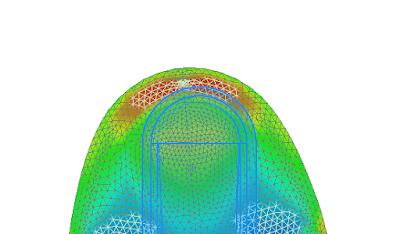
Now we have the Unwrap command.  I was surprised to find that it is a standard 3D modeling feature, and not a sheet metal command.  It is really easy to use.  You just have to pick the faces that need flattened and the software does the rest.  There are additional selections for edges that are to remain linear or rigid edges that won't deform, which are optional.  To be honest, I am still trying to master those selections.  While in the command, or editing the feature, the flatten surface will be displayed as a mesh with a heat map.  The heat map displays areas that will be under higher stresses when forming the finished shape, like the image below.


The software will then output a surface body of the flattened faces.  It even creates a View Representation where the surface body is visible and the rest of the part is turned off.  .


This View Representation can then be used to represent the flattened part on a 2D drawing.


Here is a video that demonstrates this new feature.


This is a new feature, so I haven't had the opportunity to master it yet.  I can say that there are a few aspects of the output that I am slightly disappointed in.  For example, on a few really complex parts, holes always seem to distort.  However, I can say that this is a big step in the right direction.  I am sure that my few concerns will probably be eliminated as this feature is refined and enhanced in the future.

Friday, January 25, 2019

Autodesk Nesting Utility

Since the introduction of the Product Design and Manufacturing Collection, Autodesk has strived to offer tools that would create an end-to-end solution, providing tools to go from concept to manufacturing.  For years, Inventor has been the concept design tool, at the center of the collection.  In the last few years, Autodesk added tools to better enable users on the manufacturing side.  One of the most recent additions is the Nesting Utility.

 The Nesting Utility can go from assembly to nested layout to DXF output, in just a few moments. With Inventor HSM, also part of the Product Design and Manufacturing Collection, users then can export the nest to a 3D model and use Inventor HSM to create the tool paths for the nests. The Nesting Utility is also flexible enough to handle Sheet Metal Flat Patterns or standard Inventor parts.

Until recently, I really hadn't explored the abilities of  the Nesting Utility.  I think I watched an overview video when tool was added to the Product Design and Manufacturing Collection.  Then I had a question from a customer that prompted me to really understand how the tool works.

In this case, he has been using Inventor for all of his drafting and modeling work, but he was going to be called upon to start doing some CNC programming.  So we talked about HSM, then he said, that nesting the parts into one layout would be important for him too.  At the time, I knew that the Nesting Utility existed and worked great for sheet metal components.  However, I wasn't sure if it would handle wood, which would be the application in this case.  I had an idea how we could probably cheat the system if it only handled sheet metal, but I wanted to understand the utility first.  Much to my surprise, an update to the Nesting Utility expanded the capabilities to handle standard parts and sketch only parts.

The workflow is actually pretty straight forward, once you understand how it works.  However, the system is a little picky and you need to be aware of a few things before starting.
  • For Sheet Metal components, make sure you have generated the flat pattern, even if the component does not contain any bends.
  • For Standard Parts, the utility needs to understand the thickness of the part, this is typically figured out automatically, but can be manually configured in the IPT.
  • For Standard Parts, it can only handle one feature and not the finished shape.  So user might need to model their parts differently, if they are going to nest them.
  • I have also noticed that the Nesting Utility does not differentiate between standard and construction geometry.    It might not see closed loops because of this, and may display some components as containing errors.

To start the process, it is pretty simple.  All you have to do is open an assembly.  Then right click on the assembly in the browser, and choose "Create Nest."


This will open a dialog box, where the user needs to pick a template.


Then the Nesting Utility will display a dialog box, with a list of all the components.  I have done this on some larger assemblies and it has taken up to 30 minutes, or more, to compile the list.  So just be aware that the larger the assembly, the longer this will take.  It is most likely that every component in the assembly will not need to be in the nest, so it is possible to exclude parts by right clicking on it and choosing Delete.


At this point, clicking OK will bring all the selected components into a new nest file.


Then clicking Create will begin generating the nests.


The Nesting Utility will display a dialog showing the components and the packages, which are the individual nests.


After accepting these options, the software will display the nests.  


If the raw material is not the right size, that can be corrected in the Process Material Library.  You can also get an efficiency rating for the sheets in the nest.

One lesson I learned, when working with the wood components, is to make sure that the component spacing is greater than, or equal to, the diameter of the router bit.  If it is not, you can edit the properties of the individual nest and change the Item Separation parameter.


There are a multitude of tools to adjust the nests, but I don't want to go into all of that in this introduction.  However, there is plenty of documentation to understand those options.

The next step would be to either export a DXF or a 3D model.  The Nesting Utility exports to DXF because they are easily imported into your CAM software.  However, if you use Inventor HSM, you can export a 3D model and build your tool paths, while still in Inventor.


DXF


3D Model

Here is a video demo of the workflow.


The Nesting Utility is a great addition to the Product Design and Manufacturing Collection and should be a welcomed addition for anyone that needs to nest their components.  It is a great workflow that blends right into the CAM workflow as well.