Thursday, September 9, 2021

Human v. AI Design

My favorite part of having a 3D printer is that I can print my own designs.  I really love designing stuff, printing it, and using my design for its intended purpose.  Recently, I modeled up a pretty basic phone stand.  My design wasn't anything special, I mimicked the designs of phone stands I have seen for sale.

This is my design

As you can see, there isn't anything special about it. After I printed my phone stand, I thought, "I wonder what generative design would come up with?" So I decided to run a study to see what Fusion 360 would do.

I made a copy of my design and trimmed the model down so all I had left were the preserve geometry I wanted.  With this design, I wanted to be able to rest a portable power supply under the phone, so I added a block to the design to represent a portable power supply.  I had to oversize it because I wanted to be able to slide it in from the front.


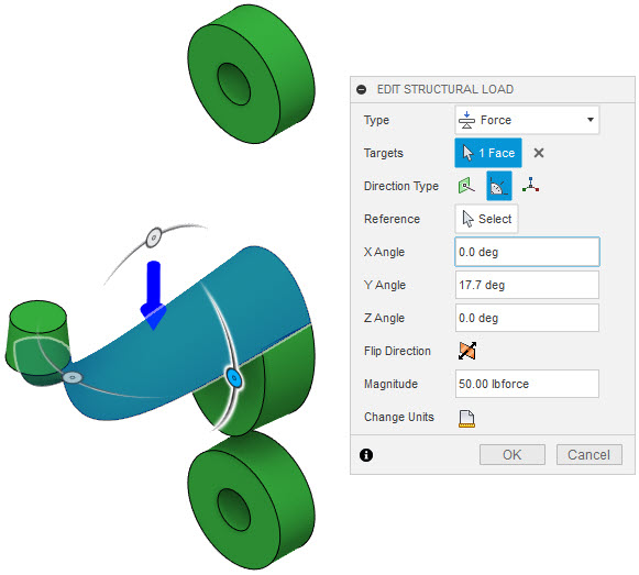
With my preserves and obstacles modeled, I was able to enter the Generative Design workspace and identify the preserves and obstacles.  The next step was to set up my load cases.  I decided to add one Load Case that represented the phone in the stand.  I figured it would make sense to have a fixed Structural Constraint that held the base to whatever surface it is sitting on.  For my Structural Load, I looked up the specifications for my phone and found that it weighs a half-pound. So I set the load to a half-pound.  From previous experience, I felt that it was likely that Fusion 360 would not be able to solve the study because the load was too light.  However, I decided to start with the actual weight and I could increase the load if necessary.  My suspicions were right and I ended up setting the load to five pounds because the first few attempts to solve the study failed.


When it came to defining the material, Fusion 360 does not have PLA in the Material Library.  For this print, I intended to use a spool of High-Temperature PLA, so I had to do an internet search for the material properties of PLA so I could add it to my Material Library.


The last step is to define the Manufacturing method.  I set mine to Additive and Z+ because that is the XYZ orientation to the print-bed that I intended for this design.  Some day I might run the study again using all orientations just to see what Fusion will come up with.


So here is my phone stand next to the one that Fusion 360 designed (in Fusion 360 then the printed models).


Let's compare key attributes of the two designs to see which one is better. To be fair, I ran FEA Simulations on both of these in Fusion 360, with the same loads and constraints.


Here are my results, listed as my design vs. Generative Designs outcome.


Time to Print: 10 hours v. 8 1/2 hours

Mass: 2.873 oz v. 2.107 oz

Safety Factor: 4.985 v. 4.744

Displacement: 0.1313" v. 0.01845"


In each case, the Generative Design model is better than my design. It can be printed quicker and weighs less. For Safety Factor, if we have a target of 2 or 3, so we don't over-engineer our parts, Generative Designs is better. I included Displacement because my intention is to have enough space below the phone so it can charge it while in the vertical position. Less displacement would mean that I am more likely to be able to fit my charging cord in the phone while in the stand.


I will say that I did make a few edits to the Generative Design model to clear up a few small issues.  First, I should have had an obstacle to represent where the charging cord plugs into the phone and an obstacle representing the phone. Since I overlooked that, Generative Design added some material in the gap where the charging cord is supposed to go. I just removed that material because I knew it wouldn't have any impact on the stand's ability to hold a phone. 


Secondly, I noticed that a portion of the main post extended beyond the base.  I didn't like the way it looked so I edited the model's Free Form feature to clean up that issue. In retrospect, it didn't have a bearing on my ability to print this model and I didn't need to perform this edit.


So this is just a phone stand and may not compare to the complexity of some of the components that you design. However, the ability for Fusion 360's Generative Design to augment my design speaks for itself. In this example, I unintentionally overdesigned a component because I was using standard design techniques. Then with input and direction from me, Fusion 360 improved upon my design. I liked my traditional design, but there was nothing special about it. With Generative Design, I have a more intriguing design that is capable of out-performing my design. I know I titled this blog article about Human v. AI design. Generative Design is a form of AI design, but the process is still driven by the user, and their skills are augmented, and not replaced, by generative design. After this test, I would say that Fusion 360 and I make a really great team. I look forward to other projects where I can leverage this tool to make me a better designer.


A video of this process can be found on YouTube


Monday, August 9, 2021

Generative Design and 3 Axis Milling

 One of my first impressions of Fusion 360's Generative Design outcomes was that the 3 axis milling outputs were too organic and looked nothing like what current manufacturers are producing.  I questioned if the companies I worked with would be willing to adopt the software for that reason.  Recently, I have come to the realization that I was way wrong in my early impression.  Part of the process of defining your manufacturing criteria is that you define the smallest mill you are going to use.  So as long as you create your CNC program with that as your smallest mill, you will be able to manufacture what Generative Design produces.  Creating your toolpaths for a 3 axis milling outcome from Generative Design can be as simple as using Adaptive Clearing to remove most of the stock then using Parallel, Scallop, and/or Morphed Sprial with a Ball Endmill that matches the diameter and length specified in the Generative Design study.

I decided to try creating toolpaths for a Generative Design outcome, using the same mill settings used in the Generative Design study.  I know this feels a little obvious because this is the way the software works.  However, I feel this is necessary to prove my first impression wrong and perhaps give fellow users more confidence in their ability to create these toolpaths.

So I had to find something that would make a good candidate for a Generative Design study.  I thought about a flat screen wall mount, and I remember I had one in a data set I have been using for years.  This design had two arms and a link.  I felt it was best to focus on just one arm.  Looking at the existing geometry, I realized that it already had well-defined preserves and a starting shape that I could leverage.


Since I was starting in Inventor, I used "Send To Fusion" to send the model to my Fusion Team project.  From there, I was able to open the model and add a couple bodies that will be identified as obstacles.

Here is a video demonstration of these steps.


My next step was to jump into the Generative Design workspace.  There I was able to identify my obstacles and preserves.  Then, I defined my 3 Axis milling criteria, including which orientations of the model I planned on having setups for, the finishing tool I planned on using, and which materials I was considering.

Here is a video demonstration of these steps.


After the Generative Design study is completed, I was able to explore the models that were created by the study.  In this case, there are two outcomes because the study contained one manufacturing method and two materials.  Fusion 360 will calculate each model's weight, volume, safety factor, and many other properties.  This allows the user to weigh different options and decide on the best model to suit their application.  In my example, I chose the one made out of aluminum because it was lighter and its safety factor was higher.

Here is a video that shows how to explore the outcomes and generate a model from that outcome.  In my workflow, I had a small area that I wanted to clean up.  This video demonstrates that process as well.

\

After the model file has been generated and cleaned up, Fusion 360's Manufacturing workspace can be used to create the toolpaths for the CNC program.  For me, the process is going to be to do a couple adaptive clearing operations to get rid of most of the excess material.  Then use operations like Parallel, Scallop, and Morphed Sprial as finishing operations using a ball endmill that matches the parameters I entered in the Generative Design study.  I am not sure what took me this long to realize that is the process.  Perhaps you saw that connection right away.  Once I realized the process, I realized that this wasn't as difficult as I thought and wanted to try it out.  Which was the motivation for this blog post.

Here is a video that demonstrates creating the toolpaths for this part.


The last step in this whole workflow was to send the completed model back to Inventor.  The main point of this blog post was to talk about creating the toolpaths for a part that was created in Generative Design.  However, since I started in Inventor, I feel like I have to end there with the completed design.

Fusion 360 lets users export an IPT from the design files.  In my case, I exported an IPT from the completed arm model.  Then in Inventor, I was able to place the new model in the original assembly.

Here is a video that demonstrates that portion of the workflow.  I also spend a little bit of time comparing the original model to the Generative Design model.


This blog post may have felt obvious.  As I stated before, I wanted to go through this process to help myself feel more confident in my ability to create toolpaths for the models created by Generative Design.  I think what took me the longest to learn was the types of toolpaths that should be used to mill these organic shapes.  Since I have learned some of the best operations to use, I wanted to share that knowledge with fellow users out there and hopefully allow them to feel more confident in their ability to program these models as well.

Friday, July 9, 2021

Inventor AND Fusion 360

Ever since Fusion 360 was introduced, Inventor users have begun asking, "When is Inventor going to be replaced by Fusion 360?"  I will admit, I had the same thought on a few occasions.  The products are so similar that you begin asking yourself, "Why do we have both?"

Autodesk describes Fusion 360 as their next-generation CAD/CAM/CAE software.  With every product we use, someone somewhere is working on the next generation of that product.  I think cell phone companies launch three next-generation cell phones a year.  So it makes sense that Autodesk, and their competitors, would be doing the same thing.  As someone that uses both Inventor and Fusion 360, Fusion 360 feels like what Autodesk would create if they could develop Inventor from scratch knowing what they know now.  

I want to purpose that we need to stop thinking in terms of Inventor OR Fusion 360 and starting thinking Inventor AND Fusion 360.  There are great workflows that support using both tools.  Currently, we can leverage both tools in CAM, Generative Design, and Simulation.  Autodesk has created several different ways to seamlessly connect Inventor and Fusion 360.  If you are using Fusion Teams, you can jump seamlessly between the two products with file associativity.

The latest way to connect the two products is through Inventor 2022's Send to Fusion command.  If you are working with Inventor 2022 and have access to at least one Fusion Teams project, you can push your Inventor model directly to that Fusion Teams project.  It is as simple as pushing a button, once you have picked the Team and Team Project.  From there the file can be placed into a Fusion 360 design file or opened.  Either way, the placed file will remain linked to the uploaded IPT.  If a new version of the file has been uploaded, Fusion will recognize that there is a new version of that IPT and prompt the user to update so they can be using the latest version of that file. 

If you want to see this in action, I have created a video that illustrates the process inside a CAM workflow.


Using Inventor and Fusion 360 gives users greater flexibility in their workflows.  The ability to jump between the products allows users to collaborate even easier, especially if they are collaborating outside company walls.  In my video, I used the example of sending the IPT to a company that is going to program and machine the part for me.  With one button, I was able to send the file, then it only took one more click to send the updated model after I changed the part.  It can't get any easier than that, right?  On the CAM side, the user was alerted that a new version was available.  After they updated, they only had to regenerate the toolpath to reflect the new geometry.

Another benefit is that a seat of Fusion 360 is more affordable than a seat of Inventor.  So if there are users, in your company, that are dedicated to CNC programming or FEA analysis, they don't need a seat of Inventor, they just need a seat of Fusion 360.  Even though I can create the CAM toolpaths with Inventor CAM and do FEA analysis in Inventor, Fusion 360 is capable of those same functions and has a smaller yearly subscription cost.

Fusion 360 will also give you access to Generative Design, which is something Inventor is not capable of at this time.  Since Inventor and Fusion 360 make it easy to share files between the products, you have the flexibility to design your preserves and obstacles in Inventor before sending the file to Fusion 360.  Alternatively, you can send the model to Fusion 360, then design your preserves and obstacles in Fusion 360.  Since, this workflow retains files associativity between the products, if the Inventor model changes, Fusion 360 can be easily updated to reflect that change.  This is such a powerful workflow and because I strongly feel that Inventor users should be looking for ways to incorporate it into their workflows, MESA has created a class on Generative Design for Inventor Users.  

Here is an overview of what is covered in MESA's Generative Design for Inventor Users course.


I still remember when I started using Inventor, AutoCAD users were asking, "When is Autodesk going to stop making AutoCAD and make me use Inventor?"  That was over 13 years ago and I don't see that happening any time soon.  I feel the same about the Inventor or Fusion 360 discussion.  So we can stop asking Inventor OR Fusion 360 and start thinking in terms of Inventor AND Fusion 360.  The two products work very well together and are so similar that users should be able to jump back and forth without much effort.  By finding ways to leverage the strength of each tool, users will be able to design and manufacture better products easier than they were just using Inventor.

Friday, July 2, 2021

Printing from Fusion 360 Gcode

If you read the last blog post, which was about creating additive manufacturing toolpaths and gcode in Fusion 360, here is a video about printing that model.


Thursday, July 1, 2021

Fusion 360 Additive Manufacturing

I am always looking for different ways to accomplish tasks because you never know when a new approach will be better.  It might be easier, quicker, or provide better results.  I find myself doing this in all aspects of life.  I drive my wife crazy because even after I decide on an approach to something, I am likely to consider alternate methods.  This idiosyncrasy is partly how I have acquired the 3D modeling knowledge I have. The latest workflow I explored was the ability of Fusion 360 to create additive manufacturing toolpaths.

When I got a 3D printer back in February, my workflow quickly evolved into designing projects in Fusion 360 and exporting an STL file.  Then I would use Ultimaker Cura as my slicing program.  From there, I could create the necessary gcode for the printer.

Fusion 360 added the ability to create additive toolpaths a while ago and I had it on my list of functions to check out.  So, yesterday I finally decided to give it a chance.  One aspect of this process that is really nice is that I don't have to worry about exporting an STL file.  I can just jump into the Manufacturing workspace and create my setup and have it generate my toolpath.

For my test, I used a design that I had previously created a setup for subtractive manufacturing.  I just created a separate setup for the additive toolpath.  It was very convenient to be able to have both types of toolpaths in the same file, which of course are dynamically linked to the actual design.  In my normal workflow, if the design changed, I would have to remember to export the STL again.

One issue I had was that there was not a default Print Setting for 1.75 mm PLA.  I had to copy one for 2.85 mm PLA and modify it to match my desired settings.  That wasn't a big issue, but it was something that I had to workaround.  I was somewhat surprised that 1.75 mm PLA was not one of the defaults, from my experience that seems to be the most common filament size.  When I created the new setting for 1.75 mm PLA, I was able to save it as a cloud setting, so now that collection of settings will follow me from machine to machine and I will not have to create it again.

I will say that the Print Settings have a ton of options.  For someone that is relatively new to 3D printing, it was a little overwhelming to see all those settings.  I am just not experienced enough to know exactly what to set for some of them.  I did change the few that I knew I wanted to change and left the rest as the defaults.

Here is a video I made that walks you through the process I used to use Fusion 360 to create my Additive Manufacturing gcode.


The next step is to actually print from this gcode.  I plan on printing this part from this gcode to see how it turns out.  I will post about that soon, so please check back to see my results.

Wednesday, June 9, 2021

Fusion 360 Machine Simulation Preview

 In October of 2020, Autodesk acquired technology from a company named CAMplete.  The technology was capable of several functions, one of the most notable was running your CAM simulation in the context of the CNC machine.  When I heard of the acquisition, I was pretty excited because I knew that this would be a great addition to the CAM workflows I was familiar with in Fusion 360 and Inventor.  My only questions were how the functionality was going to be rolled out to Fusion 360 and/or Inventor and what it would look like.

I believe we have seen the beginning of that technology being rolled out to Fusion 360.  There is nothing in the documentation that says this is the CAMplete technology, but it is pretty obvious that the new Machine Simulation Preview in Fusion 360 is based on that CAMplete technology.  

Since this is a preview feature, you will have to enable it in your Fusion 360 Preferences.  At the bottom of the menu in the left pane of the Preferences dialog is Preview Features.  If you click on that, you can then look through all the preview features or filter by Workspace.  You will be looking for the function called Machine Simulation.


Once that is enabled in your Machine Library dialog, you will now see a filter option for Simulation Ready.


If a machine that is simulation-ready is defined in a Setup, you will then see the machine when the Setup is selected in the browser or when you are simulating a setup.


That is all you need to do, you can just program your toolpaths like you would normally do.  I really like this new function.  I think it will give CNC programmers more clarity into what the toolpath will look like when running the program on the machine.

If you would like to see this preview function in action; here is a video demo I created to show how this works.
  

Monday, May 24, 2021

Inventor Feature Presets

With the launch of Inventor 2022, Autodesk added several feature enhancements that you might already be using.  One feature that really isn't new, but is now available in more commands is Presets.  I haven't covered Presets before in this blog and I recently took a deep dive into Presets to understand how they work.  I figured that I would use this opportunity to share what I have learned.

Presets are a great way to save some time if you do the same type of operations, or features, often.  I can say that you will likely find that Presets are offered in certain commands that you may not have a need to leverage them in too.  The last time I checked Presets were available for Holes, Threads, Coils, Sweeps, Insert Frame (from Frame Generator), Surface Symbols (2D drawings), and Weld Symbols (2D drawings).

The idea behind Presets is that I can save a group of settings for a specific feature for future reuse.  One of the first commands to get Presets was the Hole command.  I really wished this was available when I had my last job.  Creating .190 diameter thru-holes was a pretty common feature that I needed to create.  With the use of Presets, I could have created that type of hole and leveraged that every time I needed to create that type of hole.  

Presets can also be standardized and shared across multiple users.  When Presets were introduced, Inventor project files added a mapping to a directory for them to be shared.  


Once you define a preset, Inventor will save a file in that directory for that feature type.


Creating presets is very easy.  All you have to do is set up the feature with all the necessary settings, then you click on the plus sign at the top of the feature dialog.


Inventor will name the preset by combining the attributes of that feature, however, you can customize the name to suit your needs.


From now on, when you want to apply that feature, you just need to select the preset from the drop-down menu.  You will still be able to override any of the predefined parameters.  So you can think of this as more of a feature template that can be leveraged, but you can still modify the parameters after you apply the preset.

If you would like to see the Hole Presets in action, here is a demo video I created.

Wednesday, April 21, 2021

Inventor 2022: Model States Replaced Levels of Detail

 Inventor 2022 has been out for a few weeks now and I have used it a little bit, but I haven't fully migrated to using it full-time.  Today, I had my first introduction to the new Model States function in Inventor 2022.  I had a rough idea of what they were going to be capable of because I read a few articles and saw a few presentations on what Autodesk was looking to add in Inventor 2022.  I will say that I was blown away by how much Model States are capable of.  I was also not aware they are essentially replacing Levels of Detail.

I have been using Inventor for over 15 years and have used Levels of Detail quite often in that time.  In my current job, I teach a class in Large Assembly Management, in which Levels of Detail and Level of Detail Substitutes are a large portion of that class.  In watching a What's New In Inventor 2022 webinar, presented by Autodesk, they were talking about Model States and said how any custom Levels of Detail will be migrated to Model States when the file is opened in Inventor 2022.  This really caught my attention because I just figured that Model States would be a new way of doing some of the things that I used Levels of Detail for in previous releases and that both functions would be available.  I was wrong, Model States have replaced Levels of Detail.

As I was thinking through the new workflow using Model States, I had the realization that Model States will eliminate a frustrating behavior that has plagued Levels of Detail for as long as I have used Inventor.  When working with Levels of Detail and often when having the model and drawing open at the same time, Inventor would eventually give the user an error stating that the current Level of Detail cannot be saved because another one is currently being edited.  


 Model States do not need to be saved as you transition between them, so this should be the end of an error that has driven plenty of users crazy.

Here is a video I made that shows how to use Model States to accomplish some of your Large Assembly Management workflows.


I am excited to learn more about Model States in Inventor 2022.  There are workflows for parts where they can be used instead of iParts.  They also can help in the case of casting and machining workflows.  This is one of the biggest enhancement introduction that I have seen the last few releases of Inventor.

Tuesday, March 9, 2021

Wall Hook Update: ABS Print

I was a little worried to print my wall hook in ABS because I read plenty of posts from makers that said that it tends to warp and split during printing.  Since I already had a spool of ABS, I figured I should give it a try.

The print came out looking great.  The ABS print actually has less visible layer lines in some spots.  That might be because I used a white ABS filament compared to a matte light gray PLA filament.  


I only had one issue with this project.  When I was setting up the project in Cura, the recommended bed temperature for ABS is 80 degrees Celcius.  My printer gave me a couple messages that stated, "Heating Error, Printing Halted, Please Reset.".  I am not sure was caused it, but I will say my printer does that when I run the bed hotter.  So I consulted the specs for ABS and saw that 80 degrees were on the high end of the range.  I tried the print with bed temperatures of 70 and 75 degrees.  In the end, 75 degrees worked out well.

As I write this, I have the printer heating up to run a different project in ABS.  I will have to see if I get similar results.


ABS Hook Installed


Wall Hook In Use


Monday, March 8, 2021

3D Printing a Generative Design Model

In a previous blog post, I talked about design a wall hook for my backpack using Generative Design in Fusion 360.  The goal was to then get the design 3D printed.  Now that I have a 3D printer I am able to print this design.  I purchased a Creality CR-10 S5 and this was one model that I used to learn all I needed to know about how to get good 3D prints.

Creality has its own slicer, but I have read that a lot of Creality owners use Cura, which is Ultimaker's slicer and free.  I wasn't sure which one would be best, so I bounced back and forth between the two for a while.  I have since settled on Cura because it gives more options than Creality's slicer.

Cura will take in an STL file that I can export out of Fusion 360.  There are two ways to get the STL file out of Fusion 360.  I can either use Export or 3D Print to accomplish this.  If I use 3D Print, I can send it directly to a 3D Print Utility, I tried this once, but I don't get to save the STL to my chosen location or even name the STL.  So I just save it to a file then load it into Cura myself.  I have also learned that it is best to switch your document units to mm before using the 3D print command.


Export Dialog

3D Print Dialog

Once the STL file is exported, it is just a matter of opening Cura and inserting the STL into a project.  I have used a few slicing programs over the years and they are all pretty simple to learn how to use.  You just need to position the model on the build plate where you want it.  In my case, I had to rotate it so it laid flat on the build plate, which will minimize the number of supports it would need to build.

The first time I printed this model, I realized that it is way too small.  I do have a little bit of an issue with picturing my CAD designs at full scale.  So the second time I ran this, I used the slicer to scale the model 2x, which in retrospect seems a little too big.  I know this wasn't the proper technique.  I just wanted to quickly try it at a larger scale.  The main reason this is an issue is that the holes are twice as large.  I am okay with the scale of the rest of the model, I might have to use washers when I go to actually put this part into use.


When I was going through the Generative Design study, I chose ABS as the material for this part.  That was solely based on ABS being in the material library and PLA was not.  When I bought my printer I bought a spool of ABS and a couple spools of PLA.  The versions of this above were printed in PLA.  The larger one feels sturdy enough to use.  I used PLA to print this for two reasons.  First of all, it was already in the printer.  Secondly, now that I have a printer I have read that ABS is harder to print.  I was curious about which material is considered better, so I did a little research.  I discovered that PLA is actually stronger but more brittle.  ABS is more heat resistant, which requires higher bed nozzle temperatures.  It is very prone to warping.  

After read about the pros and cons of each, I feel that PLA is better for this design.  However, I do have a spool of ABS and I think it will be worth trying to print this in ABS just to see how it comes out.   

Here is a video tutorial that shows the process.


My First Month with a 3D Printer

I have been wanting a 3D printer for a number of years now but wasn't sure how much use I would get out of it, so it remained a "wish list" item.  Then recently, we realized that it could be used to make 3D stencils for my wife's furniture refinishing business. Initially, I was looking at smaller printers, but since my wife wanted to make decent-sized stencils, we needed a larger printer. I started looking for affordable printers, with a larger printable area, and good reviews.

After several months of research, I landed on the Creality CR-10 S5.  It has a 500 mm x 500 mm x 500 mm build area.  It was within our budget and had many good reviews on Amazon and YouTube.  So I ordered it and it took about two weeks to arrive because the printer was out of stock when I went to order it.

I was very excited the day it arrived. I knew it would take a week or two to learn all the intricacies of the printer and get it tuned for easy use. That was a little bit of an understatement. It only took about 15 minutes to assemble and get working. However, it took a bit of time for me to figure it out. There are plenty of places to learn about how to 3D print, but I was confident in this being an easy machine to use that I didn't bother watching those videos and just jumped right in. It took me about a day to get a completed good print.

My first issue was bed leveling.  The first problem is that I didn't bother leveling it properly.  I was too excited to print and I didn't quite understand the process, so I half-heartedly leveled the bed.  Once I learned how to do it properly, I developed a pretty good system and now  I check my bed for levelness several times a week.  I have seen several users highly recommend the BLTouch auto-bed leveling system.  I am a little intimidated by the process of installing that, so I am holding off at the moment.  I feel that I have a pretty good system and have the bed in a good situation.  I can say that the table I had the printer on originally was not a good table.  It was older and I think I was fighting bed levelness issues because the table was not truly level itself.  I switched to a different table and my bed leveling issues were not as bad.

Bed adhesion was also a problem right away.  This printer came with a tempered glass bed.  I thought that was great because I have read about people costly have to change build plates.  My mistake here was that I thought that the glass was designed for the filament to stick to automatically.  After just a few minutes of research, I discovered that I was wrong.  You need to do something to the bed to help the filament stick.  I chose glue sticks, mostly because we already had that in the house.  Those have worked more often than not.  I have had a few projects that still don't stick well in the corners.  However, this printer has a large print area and I am not sure if the outer corners are getting hot enough.  I have read about people using hair spray, so I tried that and it didn't work as well as the glue sticks.  I also tried covering the bed with masking tape.  That didn't work well for me.  So I think I will stick with the glue sticks.

One issue that I feel I finally have resolved is the issue of the proper bed to nozzle distance.  It also plays a part in my bed adhesion issues.  I was following the advice I have seen online of sliding a piece of paper under the nozzle and when it slides freely then I have proper spacing.  I was still having some slight adhesion issues after doing that.  What I tried this past week that seemed to make a difference is that I would still use the piece of paper.  However, I adjusted the bed to the point where I could feel the paper catching a little.  Also, I could see the nozzle scar the paper just a little.  I had done that in the past and the nozzle was so close to the bed that my first layer was not the right thickness.  So to compensate, I just used the settings in the printer to then move the nozzle up 0.1 mm.  Since my layer height was 0.2 mm, it is essentially a half step.  This has helped immensely.  In previous prints, I would find that the first layer was inconsistent, some spots would be the full layer height, and others spots would be only a partial thickness.  My last two prints had a very consistent first layer.

I know that this sounds as if this has been a challenging month, and in ways it was.  My emotional state would fluctuate from ecstatic that my prints were going well to feeling like I made a mistake buying a printer.  Sometimes that was during the same print.  I really have enjoyed having the printer and feel like I have learned a lot.  If you are going to buy, or have just bought your first printer, hopefully, you can learn from my mistakes.  

I can also say, that I have learned that fine-tuning your printer can be as unique as people's taste in food or music.  What works great for me may not work well for you.  I tried to find optimal settings for bed and nozzle temperatures.  As I tried to replicate those, I found that I have had to run mine a little hotter than some recommended settings.  Maybe as I get more confident, I will start adjusting those down.  I have already started to tweak my normal bed temperature down because I was trying to compensate for bed leveling and adhesion issues.

I do plan on sharing some more lessons I learn as I go about doing more 3D printing, but for now, here are some pictures of my failures and successes.

3D Stencil

Church Window Decor

Wall hook that I printed with a bad extrusion feed rate setting

An example of my bed adhesion issues

My first successful print, the obligatory 3D Benchy


Monday, January 25, 2021

A Generative Design Story

Over the last several months, I have really worked to learn all I could about Generative Design in Fusion 360.  However, there are only so many tutorials and sample files that you can work on.  I wanted to use Generative Design for a real design project, but my job doesn't always provide me opportunities to work on design projects.  So I decided to create one of my own.  I figured I could find some product I could use at home or work that I could redesign with Generative Design.  I decided to use Generative Design to create a hook for me to hang up my laptop backpack.

In my home office, I really don't have a place for my laptop backpack.  I was considering going out and getting a 3M Command hook, but I thought designing my own with Generative Design and 3D Printing the hook would be more fun.

When using Generative Design, we have to define several elements:

  • Preserve Geometry
  • Obstacle Geometry
  • Load Cases
  • Manufacturing Methods
  • Materials that we are considering making this design out of
Preserve Geometry
Preserve Geometry are solid bodies that will be part of the final design.  For my hook, I figured that the preserve geometry would be the area around the two mounting holes and a lofted shape to hang my backpack on.  Once identified as Preserve Geometry bodies, Fusion 360 will display them in green.  Below is a screenshot of the preserves from my wall hook.


Obstacle Geometry
Obstacle Geometry are solid bodies that represent areas that the new geometry has to avoid.  It can be mating components or an area that needs to be avoided.  For my hook, I created a simple representation of the wall that the hook will be mounted on and the handle of my backpack that will hang on the hook.  Fusion also has a specialized tool called Connector Obstacle.  The purpose of this command is to create obstacles for mounting hardware and tool clearances.  In my case, I used Connector Obstacles to represent the mounting screws and the necessary clearance to allow a screwdriver to place the screws.  Once identified all Obstacle Geometry will be displayed as red.  Below is a screenshot of the obstacles from my wall hook.


Load Cases
The Generative Study will need one or more load cases defined.  These contain structural loads and constraints that represent the forces that the part will encounter in the real world.  In this study, I have one Load Case.  My constraints are fixed constraints that will hold the part to the wall.  I have two loads, one of which is gravity.  The other is a static force on the surface that the bag will be hanging from.  Initially, I weighed my backpack to get the force accurate to reality.  I used 15 pounds.  My first few attempts to solve the study failed.  I realized that the force was too small for Fusion 360 to solve the study, so I upped the value to 50 pounds.  This will over-engineer the part but isn't necessarily a bad thing in this case.


 Manufacturing Methods
Generative Design is capable of creating parts with several different manufacturing methods in mind. The idea behind this project was to create something with Generative Design and follow it all the way through to a physical product.  With this product, I figured 3D printing or 3-axis milling would be the best methods.  I don't have access to either type of machine, however, I figured it would be easier to find someone to 3D print the part for me, so I chose that method.  There are a couple parameters that will be considered when using Additive.  We can evaluate different build directions as well as account for Overhang Angle and Minimum Wall Thickness.  When picking orientations, you need to consider the X, Y, and Z orientation of the model.  In my case, I used Y+ and Y- because the back face of my part is flat and is on the XZ plane.


 Materials
Since I chose 3D printing as the manufacturing method, I should pick a material that can be used in 3D printing.  PLA is one of the most common materials for 3D printing but is not in the Material library.  I could find the material properties of PLA and use those to define PLA in Fusion 360.  Another option would be to pick a different material.  ABS is part of the material library, so I chose to use that material for this study.


After all of the criteria are identified and entered, it is just a matter of solving the study.  Depending on how many Load Cases, Manufacturing Methods, and Materials I choose, Fusion 360 could take a couple hours to fully solve the study.  However, the software will display iterations of the solutions as they are completed.  In my case, it didn't take long to solve my Generative Study, since I only had one Load Case, one Manufacturing Method, and one Material.

As the results are displayed, you can look through the possible designs and different attributes of each.  As you find designs that you want to further evaluate, you can export them to their own design.  My first time through, I ended up getting this.


I realized that I over-designed the hook portion, which was identified as a preserve.  I decided to modify the preserved section of the hook and ended up getting this.


I think this came out looking pretty cool and  I am excited to get this 3D printed.  Check back here in a few weeks after I have a chance to get this printed because I plan on creating a post related to the 3D printing of this part.

If you want to see me walk through the design, here is a video that walks through the process.