Monday, December 19, 2016

Inventor Guided Tutorials

Over the last couple of years, Autodesk has initiated a move to slow down in-house training and support content and began encouraging users help their fellow users.  The Discussion Forums have been around for a really long time, and will always be a great way to get help.  A few years ago, Autodesk launched Screencast.  I describe Screencast as Autodesk's version of YouTube.  They then created the Autodesk Knowledge Network, by merging the forums with Screencast and adding the ability for users to write articles of their own.  With the release of Inventor 2017.3, Autodesk added another tool to that toolbox.  In Inventor 2017.3 users can now create their own guided tutorials.  


As an instructor, I immediately saw this as great way to transfer knowledge.  I just created my first Guided Tutorial, and it couldn't be easier. To be honest, previous versions of Inventor could do this, but it wasn't easy.  Autodesk knew how difficult it was, and have done a great job at making the process easy.


The process really starts outside of the software, with a planning stage.  It really is important to have a plan, or script.  I scripted out what steps a user would have to take to model the part in question.  That is important because the tutorial will be divided into Tasks, then into Steps.  Each task can have an overview Screencast attached. So my next phase was to record the Screencast videos for each Task.  It is worth noting that the tutorials look for a local WEBM file, so you will have to download the Screencast after recording them.  

After the planning and creating the Screencasts, it was time to dive into Inventor to create the tutorial. It is a very simple to create the Tasks and break them down into steps. I like how I can associate commands to each step, so if a user is not sure what to do next they can be prompted with highlighted commands. Each Task can have a starting file, which is helpful if users join a tutorial after a Task or two. This files can be uploaded, or Inventor can capture the file that is the current model in Inventor. I have not tried enough of these to say which is best. I think it is great that you can capture the current model, but I have a feeling that I will eventually transition to having a saved file for each Task to upload.

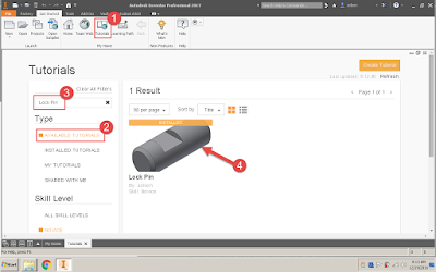
Once the tutorial is created, it can be shared publicly or privately, through A360. I shared my first effort publicly. Search for my tutorial by going to the tutorial page, inside Inventor 2016 or 2017, and search for "Lock Pin."


Autodesk continues to give users great ways to help the larger community of users around them. The Guided Tutorials are another great way to do this. I think it is a great training option whether that is training in general or for a company specific workflow. So I urge you to check them out.

Monday, October 31, 2016

CAD with a Dad

I have been fortunate recently, my company has been willing to allow me to take time out of my work day to teach Fusion 360 to the homeschool co-op my children attend.  I had one hour, once a week, over 8 week to work with 10 kids that are between 10 and 13 years old.  This has been great for me and the kids in many ways.

First, I am pretty passionate about STEM education.  As a parent of three kids, I recognize that careers in STEM fields are a great path to success for them, knowing that some of the students are destined for other career paths.  Since Fusion 360 is 3D modeling, I see that this experience is a good place for the students to get their first connection with 3D modeling.  Whether they want to go into mechanical design and engineering, or 3D animation, the skills they learn in this class is going to lay the groundwork for the skills they will develop for those careers.

For me one of the greatest moments is to see my 12 year old son help his classmates.  I  started teaching him Inventor a couple years ago.  Grand total he has about 10 to 20 hours of instruction, and about another 10 to 20 hours of just letting him play in the software.  The first week of class was a tough class because nearly half the class needed additional one-on-one help to complete the exercise.  After a few minutes of helping each student out, I looked at my son and told him to see if he could help the other students that still needed help.  He was able to help a lot of students.  He got a great confidence boost to be able to help his classmates.  So beyond the CAD experience he gained, he gained experience as an instructor.  I was very proud to see that he still possessed the skills that he and I worked on previously.  He has told me on countless occasions that he wants to do what I do, and having this experience definitely reinforces that feeling.

This opportunity has also allowed me to share my knowledge, which is something I love to do.  I have built up a wide variety knowledge over the years, and I enjoy sharing it with the people I come in contact with.  The students I have in class have been very eager to learn Fusion 360.  It was great to seek the spark during one specific class.  I was showing them how to create 2D drawings from their 3D models.  I realized that this is not something they need to know a lot about, so I took some time and showed them reality capture and virtual reality.  That really seemed to grab their attention.

Most of the class was really excited to hear how ReCap 360 could be used to take pictures and turn it into a 3D model.  My desktop is a screenshot I took from a point cloud I made in ReCap 360 of a Lego Star War ship my son put together.  People always recognize the model and ask about it.  The students were amazed at what I was showing them.  Then, progressed to show them that some models can be rendered into a stereo panorama.  That stereo panorama could then be viewed in an app that would immerse the viewer in the model.  That really got them excited to what we were talking about.

I don't know if any of them will go on to careers in science, technology, or computer animation, but I feel great about being able to help them take the first step down that path.

Here is a slideshow highlighting work that they did on their own, without direction, following their own inspiration.


Monday, September 19, 2016

Factory Scope v. Member Scope

iParts and iAssemblies in Inventor are a great way to create a collection of parts or assemblies that are similar but have a certain amount of uniqueness.  I have created several videos that demonstrate how to create and work with iParts.  One topic that I have not mentioned before is Factory Scope v. Member Scope.  I think this is information can be very valuable when working with iParts and iAssemblies.

Recently, I was working with a customer while he was adding a member to an iPart.  He continually jumped between sketches and feature and the iPart table.  We was checking the names and values of dimensions, then going to the table and changing the value for the new member.  After doing that a few times, he asked me, "Is there any way I can change the values in the model without having to go to the table?"

To which I replied that there was.  I pointed him to the Factory Scope/Member Scope setting.  For users that are not familiar with the purpose of this setting, it allows a user to specify if a change is for the entire factory(all members) or for a specific member.  By default Inventor is set to Factory Scope, that means as the user changes the model, those changes are applied to all members.  If the user changes that setting to Member Scope, the edits that the user performs are applied only to the active member of the iPart family.

Member Scope works great for editing the parameters already on the table, but also can be helpful when controlling feature suppression.  You are allowing Inventor to control and edit the table for you as you make changes.  It is really interesting to see the impact on the table as features are added while in Member Scope.  All the user has to do is add the necessary feature(s) and Inventor will handle adding the parameters and feature controls to the table.

Here is a Screencast that demonstrates the Power of Member Scope:

Tuesday, August 16, 2016

Configuration in the Hands of Your Customers

Autodesk has such a big library of products, it is difficult to keep tabs on all the products and what they do.  When I first saw Configurator 360 at AU several years ago, I was impressed.  At the time the product was new and Autodesk has developed the product significantly since its introduction.  I think it is a great product and can be useful to a lot of companies, so I have been spreading the word about Configurator 360.


Configurator 360 allows Inventor users to upload configurable models to a web site.  That web site can then be shared with customers or sales staff.  Customers then can customize the model and download their model and request a quote for it.  The main types of models that users upload are designs with iLogic Rules, but the model can be just a parameter driven part.  


The Configurator 360 site administrator can control a wide variety of preferences for all models or specific to designs.  For example, customers can download their customized design in a variety of formats, everything from STEP and IGES to Catia and Revit files, along with the native Inventor model.  The site administrator can pick and choose which file formats users are permitted to download.  I strongly recommend disabling the Inventor download because those files will contain the intellectual property of your company.  However, I have set as a possible download on my demo site, just to show the exhaustive list of downloads.

Here is a video I made that gives an overview of the Inventor to Configurator 360 workflow.


Here is a line to a design that I typically use as a sample for iLogic and Configurator 360


Autodesk has done a lot of development around the quoting capabilities of Configurator 360.  They have made incremental changes along the way.  Now, users are able to upload a quote template, complete with images of the customized design.


One of my favorite functions of Configurator 360 is the Accessories.  This allows users to author components as optional accessories.  The process starts in Inventor by creating a Joint between the main design and the optional component.  The Configurator 360 Add-in for Inventor will help split the Joint definition to the two models.  After both are uploaded, users can drag and drop the accessories on to the design, and the Joint definition will place the optional component on the assembly.

This link is to a design that includes accessories.

If you are selling customizable products Configurator 360 would be a great addition to your CAD tools.

Tuesday, July 19, 2016

Autodesk Fusion 360: Inventor's Little Brother?

Have you heard of Autodesk Fusion 360?  It has been around for a lot of years, but some people still have not heard of it or don't know much about it.  Autodesk has launched several programs to drive up awareness and usage.  I have been using Fusion 360 off-and-on since it's launch.  One reason I did not fully utilize it right away was because I didn't see how this could be an improvement over Inventor.  I have realized that I was misinterpreting its purpose all along.

I always call Fusion 360 "Inventor's Little Brother."  That is because its root function, 3D modeling, is so similar to Inventor, so much so that  I was able to use Fusion 360 right away.  There are a few difference between the two.  For example, Fusion 360 only has two file times F3D and DWG.  Anything 3D, part or assembly is modeled in a F3D file.  The 3D environment is similar to Inventor's multi-body parts.  

Another reason that I call Fusion 360 "Inventor's Little Brother," is that it could not do everything that Inventor could do.  That has changed over time.  I still feel that Fusion 360 is not a replacement for Inventor, but it does have a place in the 3D modeling and manufacturing world. 

Who can get the most out of Fusion 360?

The strongest usage category is in education.  I have mentioned before that I have been working with my home-schooled children to teach them Inventor.  Realizing that Fusion 360 would have been easier to teach them, I wish I could go back and start teaching them Fusion 360 instead.  Because of the similarities between Inventor and Fusion 360, I see students using Fusion 360 developing skills that will transfer to Inventor after graduation.

Fusion is also a great tool for home-use.  During classes, I am often asked if it is possible to use Inventor at home.  Students either need to take work home, or want to use Inventor to design home projects, such as decks and home improvements.  The commercial license of Inventor does have provisions for users to have a license for home-use.  One issue that most users face is that their home computer is not powerful enough to run Inventor.  Fusion 360 is well suited for the home projects. The product is free to start-ups, hobbyists,  and enthusiasts.  So Fusion is a great tool for designing your deck, home addition, or your idea for the next big thing.

Can I use Fusion 360 along Inventor and AutoCAD?

Lost of users do not know that Fusion 360 is actually included in their Product Design Suite.  It is just a matter of the Software Administrator granting access to that product through the Subscription Center.  I am disappointed that Fusion 360 will not read an Inventor IPT directly.  I has to translate the file.  If going from Fusion 360 to Inventor, users have to export to a generic format.  I recommend STEP for this.  However, Inventor's Direct Editing commands can be used to modify the model if necessary.

I do see some great workflows for 3D AutoCAD users.  I usually try to talk people out of doing 3D modeling in AutoCAD because it can be a headache.  However, with Fusion 360 modeling is significantly easier.  Now that users can create drawings in Fusion 360, I see that it would be easier for users to model their parts in Fusion 360, start the drawing in Fusion, then export to a DWG that they can finish in AutoCAD.

What is Fusion 360 capable of?
Fusion 360 has a lot of functions that Inventor does have.  There are a few limitations when you compare the two head-to-head.  However, Fusion 360 can perform all of the following:
  • 3D Modeling, including Free Form Modeling
  • 2D Documentation of models
  • Finite Element Analysis
  • Rendering Images
  • Animations
  • CNC Tooling
The bottom line is that Autodesk has put a lot of development effort into Fusion 360.  Even if you do not qualify to use the product for free, Fusion 360 is only $300 per year.  It is capable of performing most of the operations that designer would need with a small price tag.

Here is a Screencast I made that demonstrates Fusion 360's capabilities.

Monday, June 20, 2016

My ASME iShow Experience

Last week, I had the privileged of attending the ASME iShow.  For anyone not familiar with the ASME iShow, it is a design competition for socially conscious products.  My role at the show was to offer consulting on how Fusion 360 could help the teams design their products.  

This year the ten finalists had a wide array of products that would impact people in multiple different ways.  Below is a list of the finalists:

MOTI
MOTI is an IOT device that will help people live happier lives, one habit at a time.

PayGo Energy
The Pay Go Smart Meter will help people in developing countries buy clean burning fuel on a pay-as- you-go basis.

Agua Pallet
Agua Pallet is a pallet that can deliver aid, then be converted into a hand cart for transporting water and other goods.

Otter Warmer
Otter Warmer is a newborn conductive warmer designed to treat premature newborns vulnerable to hypothermia.

The CRAPPER
The CRAPPER is an affordable, water-less composting toilet that will safely treat human waste.

NODE
NODE is a low cost, GSM/GPRS enabled, Arduino based, rugged universal data monitoring unit.

Stove Trace
Stove Trace is a cloud-based remote monitoring system for clean cook-stoves, and offers financial incentives to rural households to use the clean cook-stoves.

AMPARO
AMPARO is redefining prosthetic care by creating a socket that is easier to fit, thus shortening the wait time for prosthesis.

Hydorsac
The Hydrosac is a flexible hydroponic/aquaponic system.

Buoy
Buoy is a connected whole-house device that gives homeowner's leak detection and detailed data on water consumption.

PayGo Energy, AMPARO, and Buoy received grants to further their work.  All of the products at the show were all deserving of recognition for the impact they could make to society.  All the teams received great advise from a host of experts on how to get these products to market.  I really enjoyed the product pitches on Thursday afternoon.  I like the show Shark Tank, and the pitch process was a lot like that.


Friday, June 17, 2016

Current Survey Technology: Part 3 The Results

It does pain me to say that I was not able to get a good model from the drone photos that day.  I really wanted to post the model and say, "Look what we were able to do!"  But we were not able to get that model.  I would not say that the efforts were wasted in anyway.  As long as you learn lessons to improve your process and efforts in the future, the project is not a failure.

So what are the lessons we learned?

Lesson #1:  You need more than 31 photos

I always try to get a minimum of 50 photos.  ReCap's maximum of 250 photos really is best.  I got about 31 then let my son fly the drone.  His flight ended in a tree, and it took us about 30 minutes to get the drone down.  I guess we could have try to fly again.  However, I only have two batteries and was worried that I was low on power.  The model of drone I have behaves poorly when low on power.
Lesson #2:  Pick Frisbees of VERY different colors

When I grabbed a Red and Pink Frisbees, I thought they they may seem too similar in the photos.  Then I thought that because the colors were significantly different I would be okay.  From the vantage point of the drone, with the sun glaring off the them, it was at times difficult to tell the red from the pink.  If I had trouble, I have to assume the software had trouble with telling them apart.

Lesson #3:  My hobby quality drone does not fly stable enough for this process

I love drones.  For me the appeal is equally how much fun they are to fly and the aerial photography and videos.  My drone is so light and is at the mercy of the wind.  We only had 6 MPH winds that day and my drone was still pushed very strongly by the wind.  Most professional quality drones have GPS and flight planning abilities.  Where those are not a mandatory feature for this process, they can make it easier to fly the site and can improve the quality of the results.

Lesson #4:  My kids love to run around A LOT

If you look in the photos, my kids did not stay in one place.  In fact, they were all over the field, and I have the pictures to prove it.  ReCap has no way to filter out my daughter in the photos and work around her.  To ReCap she is a feature in the field and tried to match and her surroundings in the photos.  So as she went from end to end of the field, ReCap was assuming she was stationary, and this movement confused the results.  For ReCap to work right, you really want to try to keep the area clear, as much as reasonable.  If I had 250 photos, the movements by my daughter would not have confused ReCap as much.

I was so disappointed that I did not get some really meaningful results.  I know the process works, I have seen the process work.  I guess it is safe to say that you will not be seeing any advertisements for Olson & Kids Surveying anytime in the future.  Well maybe if I can convince my wife to let me get a professional quality drone...Just kidding.

Thursday, June 2, 2016

Current Survey Technology: Part 2 Data Processing

The Processing of the Data is pretty simple, thanks to the ReCap 360 Pro workflow.  On the ReCap 360 Pro website, I can start a new "Photo to 3D"  project.  All I have to do is upload the photos identify the control points.

When I pick a control point in a photo, I can then enter the coordinates for that point.  I can even enter the information in Latitude, Longitude, and Elevation format.  In my case, the MapIt - Mobile app gave me the Latitude and Longitude, so I had to use the USGS website to get the elevations for my control points.

When identifying the control points, it is feasible to identify the points in as many photos as possible.  I have tried this in the past, and it has really overloaded the system.  Autodesk's official opinion is that you are to let the software auto register the photographs.  Which is what I would do if I was not trying to properly geolocate the model, and have it scaled properly.  So I try to identify the control points in about 3 photos.

After the manual registration process, I can pick my output file types and let the system process the model.  When it comes to output files, I always pick RCS and ORTHO for Survey based models.  The RCS can be loaded into the ReCap desktop application.  I will sometimes include the RCM, which is the Autodesk Memento file format.  I will occasionally include this so I have it if I want to load the model into Memento.

Here is a Screencast that demonstrates the process.

Wednesday, May 25, 2016

Current Survey Technology: Part 1 Data Collection

The current landscape of survey and survey technology is dramatically changing very quickly. What used to take crews of highly skilled individuals days or weeks to accomplish can be achieved in minutes, with one or two individuals. I thought it would be fun to take the next couple blog posts and outline what is possible with the current technology, and how this can be done with smaller crew of people with a different skill set.

 I was especially excited for this topic because it blends a lot of my passions together. I am a little bit of a technology junkie. I am always interested to see the newest technology and ways are using said technology. This topic also gives me the opportunity to fly my drone.  I caught the drone bug when working with a customer on a project.  Now, my son and I both have drones. Don't worry, I am fully complaint with the current drone laws. Lastly, my kids are very interested in what I do. My two oldest are home-schooled and a small part of their curriculum is what we call "CAD with Dad." CAD with Dad is time we set aside for me to teach them what I do. My oldest (12) has been using Inventor for over a year now, and my middle child (7) has about 6 months of experience.

This post is going to be dedicated to the data collection phase of our project.

The Team


Steve (Me)
My Son (12)
My Older Daughter (7)
My Youngest Daughter (2)

So you can see that, I am the only experience person on the team.  I have zero experience with traditional survey techniques, but I have seen the process many times.  I have a very good understanding of the key steps of a survey using the newest technology.  Realistically, my youngest was along for the ride, and she gets really upset when anyone goes somewhere without her.

Our Equipment 
My Cell Phone
The main role of my cell phone is to use a GPS App that would give me the coordinates of a few select points.  In this case, I used MapIt Mobile.

My Drone


My Drone is a Syma X8G.  It is a toy/hobbyist model.  I got it from Amazon.  I does not have any GPS or First Person View (FPV) capabilities.  So it is nothing special, there are a whole host of models that are better suited for this type of procedure.  However, this was a good model that fit into my budget and is a lot of fun otherwise.

Different Colored Frisbees


This is a key element to the process, but they do not need to be Frisbees.  It is important to have points with known coordinates.  I chose to mark them with Frisbees, but anything would work.  It just so happens that we had some Frisbees laying around that were different colors.  I feel that it is good to have them be uniquely identified.  The software will work better when it can tell the difference between your markers.  Frisbees are great because they lay flat, and will not give you a raised section in your resulting point cloud.  I have also seen people use the lids to 10 gallon buckets or a large white X on the ground.  If you plan on flying an area multiple times, it will be beneficial to have the markers held in place in some fashion.  Spray painting markers are a good idea as well, there is just the issue of the how permanent the paint will be.  In some smaller projects, I have used round stickers.

The Job Site
There is a nice open field less than a 1/2 mile from where we live.  I figured that would be a nice open field to perform this task on.

The Process
We laid out the Frisbees, being careful to note the coordinates of the Frisbee locations.  My youngest wanted to pick them up and move them, which would not be a problem for a typical survey crew.  We then flew the drone over the site, trying to make sure that we got the Frisbees in as many shots as possible.  Since my drone does not have the First Person View (FPV) capabilities, we had to just hope that we got them in the pictures, which we did pretty good.  For some extra shots, I had my 7 year old, take some pictures with my cell phone.

My goal was to get as many shots as I could.  ReCap has a limit of 250 photos per task.  In our attempt we did not get nearly that many for two reasons.  One my drone is so light, it gets pushed by the wind pretty severely, so it was hard to control it around the project site.  The other reason is that my son, how is a pretty experienced drone pilot, flew the drone into a tree and got it stuck.


These two issue are examples of why a professional quality drone would be best for these tasks.  With drones that have GPS capabilities, users have the ability to program a flight plan, and the drone will fly itself.  Also, these drones can take measures to adjust to stronger winds.

In my next post, I will talk about the procedure to take the photos into ReCap 360 to generate a point cloud.

Tuesday, May 17, 2016

A Quirk With iParts

Recently, I received an email from someone that saw one of my videos on YouTube.  They had watched the video that talked about how to read the iPart Table to get values for other components.  They had successfully copied the code and applied to their model.  However, they were getting an error stating that Inventor could not read the iPart table. 

The error message really through me because he clearly had an iPart and he had the correct syntax.  I had asked this user to send me his model so that I could see it first hand, and maybe the source of the problem would hit me.  While I waited, I happened to stumble upon this persons Inventor Discussion Group post regarding separate question on this model.  In reading his Discussion Group thread, I realized that the component that is giving him grief was not originally an iPart.  He had modeled component the component as a standard part then placed in the assembly.  After that had been done, he had converted the part to an iPart. 

Having that information, I realized the source of the problem.  Inventor has a quirk with iParts.  If you place a standard component in an assembly, then make that component into an iPart, Inventor does not realize that it is an iPart.  It will look like an iPart, but some of the iPart behaviors will not work.  My theory is that when an iPart is placed, certain flags are trigged that enable the iPart behaviors.  Since the change to the part happens after it is placed, the flags do not get triggered.
The solution to this quirk is relatively easy.  The component just has to be replaced with itself, using Component Replace.  When browsing for the component to be the replacement, just pick the same part file.  Now the flags will be triggered.  The only problem I have ever had with this is that the constraints always are broken.   Once they are repaired, the component will behave like an iPart. 
Having shared the source and the fix of the issue with the user I was working with, he applied the fix and his iLogic rule began working as designed.

Here is a Screencast I recorded to illustrate the issue and proper fix.


This is an issue that has been around as long as I have been using Inventor.  I run into about two or three times a year, and I don’t know if many people know or understand the issue.  So I wanted to share this with all of you.


Thanks for reading.       

Tuesday, May 10, 2016

Copying iProperties from Model to Drawing

Recently, a customer asked me if it were possible to use iLogic to copy certain iProperties from their model to the drawing.  They use certain ones on the title block, but want them in the drawing so they can be searchable in Vault.  After thinking about what the code would look like for a little while, I realized that Inventor is capable of doing that right out of the box.

In the Document Settings of an IDW, you can select properties that should be copied from a model.  It works right out-of-the-box on standard iProperties.  Custom iProperties will need a sample file so that Inventor can build the mapping.

I then realized these setting only produces a one-time push.  That is when I discovered the command to "Updated Copied Properties."  It was at that moment that I realized that I could automate the process through some iLogic.  I have to give a big "kudos" to the "Being Inventive" blog.  The heavy lifting of the syncing is thanks to the code that published.

You can see the original "Being Inventive" blog post HERE

You can download the text to the Update Copied iProperties External iLogic rule HERE

Here is my Screencast video that shows how to set this up.

Thursday, May 5, 2016

The Power of Almost Zero

Over my years of using Inventor, I have found times and scenarios where I need a dimension to be 0 or almost nothing.  For those times, I have begun using 0.001 as my personal approximate 0 value.  It works for both inches and millimeters.  Recently, I even found it useful on an angular dimension.

The beauty of this value is that it relatively unnoticeable on drawings and models.  If the geometry gets dimensioned on a drawing, the precision of the dimension should round down to a 0.

So where can the Power of Almost Zero be leveraged? 

My original discovery of the Power of Almost Zero was when I began using iLogic.  The specific design had configurations where a particular value or parameter would be 0 and other positive values.  I created a sketch driving the dimension with a parameter.  I found that if I set the parameter to 0 then changed to a positive value; the dimension would randomly push the geometry the wrong way.  I knew then that I had to find a way to get the geometry to stay in the same relative direction of the geometry that I was dimensioning from.  That is when I figured if I used a value such as 0.001 instead of 0, my geometry would stay on the same side of the geometry I was measuring from.

I have had scenarios is sheet metal models where I need flanges to touch.  If they touch, Inventor will “weld” the material in those spots and not flatten the part.  However, if there is a 0.001 gap, the part will be able to flatten.  I would have to say that my most common use of 0.001 in sheet metal models is as the Gap value for the Rip command.


My previous post referenced a way to use 0.001 as an angular limit to a Cylindrical Joint. 


I truly believe that the Power of Almost Zero can be used in all kinds of ways.  I would love to hear ways other people have leveraged this power.   

Tuesday, April 26, 2016

Restricting Rotation in a Cylindrical Joint

Recently, I was showing a class how to constrain an assembly using the Joint command.  For this example, I was using a cylinder subassembly.  Typically, the piston will spin when using a Cylindrical joint.  When I was showing this to may class, I began to think of how some simulation software packages allow use to lock degrees of freedom in joints.

While looking at the options for the cylindrical joint, I noticed that I could not lock the degree of freedom, but I could apply limits.  My first thought was to apply 0 deg for Start, Current, and End values.  When I did this, I was still able to spin the part.  Then I realized this would be a good application of the "Almost 0 Factor."  I use .001 as a value to represent almost 0 in Inventor, I call it the "Almost 0 Factor."  I will write a blog about the "Almost 0 Factor" some day soon.  When I applied .001 deg as the end value, I got the part to slide, and only rotate a small about.  The small amount of rotation was acceptable because you will never notice the rotation.

Here is a Screencast I made that demonstrates the process and outcome.


Thanks for reading,
Steve

Wednesday, March 16, 2016

iProperty Compliance Through iLogic

A common request I hear from CAD Managers is for a way to force their users to fill in all the necessary iProperties on models and/or drawings.  I still have not found a way to make this happen, but I have a way to use iLogic to "nudge" users toward iProperty compliance.

The solution is fairly simple.  First, you need to have an iLogic Form that has all mandatory iProperties, a Global Form would be best for this.  Then you can create a rule that will display that iLogic Form.  It is a pretty simple rule, just one line based on the Show Global Form snippet.

iLogicForm.ShowGlobal("My iProperties", FormMode.Modal)

Once the form and the rule are written, Event Triggers can be set for the events that should trigger the rule.  The "After Open Document" would be a good choice for showing the iProperty Form.

Another element that can be added to take the solution to the next level is a rule that will check to see if the iProperties have a value assigned.  There are a couple ways to do this, but the simplest way is to test the length of the string to see if it is greater than 0 characters.  In the rule that tests for values in the iProperties, it is important to have a counter to count how many empty iProperties have been found.  Once all the properties have been tested, an If/Then statement will be needed to run whatever procedure is determined should occur if empty iProperties exist in the file.  There are several options here, but at the very least the iProperty Form should be displayed.  Here is a sample of what that rule could look like.

BlankProps = 0

If Len(iProperties.Value("Project", "Part Number")) = 0 Then
    BlankProps = BlankProps + 1
End If

If Len(iProperties.Value("Project", "Description")) = 0 Then
    BlankProps = BlankProps + 1
End If


If BlankProps > 0 Then
    iLogicForm.ShowGlobal("My iProperties", FormMode.Modal)
End If

It is then necessary to set an Event Trigger for the checking rule, "After Save Document" is a good choice for this.

Then all of this can be rolled into a part, assembly, and/or drawing template.

Below is a video that demonstrated the process from beginning to end.


Announcing MESA U Extension Days


For those of you that thought you had to wait until this fall for you next MESA U experience, your next MESA U opportunity is just around the corner. MESA is introducing MESA U Extension Days or MESA UX. MESA UX will be held select days April, May, and June. Each day will feature two classes that are a hands-on, deeper dives into topics we discussed at MESA U. 

I will be teaching classes on Customizing Inventor's Content Center, Configurator 360, and ReCap. 

For more information, please click on the following link to our schedule and class list. https://lnkd.in/dWU2fhm

Friday, March 11, 2016

Point Clouds in AutoCAD

Since point clouds have been introduced to the CAD world, users have been thinking "Point Clouds offer a great deal of information, but how can I use it to start my CAD model.  The 2016 release of AutoCAD has added a great set of tools to enable users to begin their CAD model from the point cloud.  These tools include how to extract edges and corners (points) from interpreted planes in the point cloud.  The most useful tool is the Extract Section Lines command.  This allows the user to create a section plane, and extract geometry of the point cloud to the section plane.

 I recently was asked to help a customer take a ReCap point cloud to AutoCAD to help develop elevation views.  I struggled to find any good help on the new tools.  To help the customer I recorded a Screencast of the work flow.  I though a lot of people could find the workflow helpful, so I recorded a version of the Screencast that shows the process with the Tech Shop sample ReCap file.

The video can be found on the Autodesk Knowledge Network HERE


Thanks for reading,

Steve

Welcome

Welcome to the It's A CAD World blog.  In this blog, I plan on sharing anything I find interesting related to CAD and engineering.  Currently, I am the Manager, Training Services for MESA.  MESA is located in the Pittsburgh area and specializes in helping our customers get the most out of there Autodesk software.  I have been using Autodesk products since 2006.  I started with Inventor, AutoCAD and the Vault.  I started with MESA in 2008.  During my time there, I have expanded my knowledge to include Fusion 360, Showcase, AutoCAD Civil 3D, AutoCAD Map 3D, InfraWorks 360.

I love what I do and I love to share my knowledge.  I am even teaching my 11 year son and 7 year daughter Inventor.  I hope this blog develops into a great source of knowledge for everyone.

Thanks for reading,
Steve